Cable driven sliding door actuator

a sliding door and actuator technology, applied in the direction of door/window fittings, wing operation mechanisms, constructions, etc., can solve the problems of not providing 552 patents do not provide a remote control slider connectable to an existing sliding patio door, etc., to achieve low manufacturing cost, easy and efficient manufacturing and marketing, and low price of sale

Inactive Publication Date: 2005-07-19
SMILEY EDWARD D
View PDF21 Cites 34 Cited by
  • Summary
  • Abstract
  • Description
  • Claims
  • Application Information

AI Technical Summary

Benefits of technology

[0016]It is therefore an object of the present invention to provide a new and improved sliding door actuator that has all of the advantages of the prior art sliding doors and none of the disadvantages.
[0017]It is another object of the present invention to provide a new and improved sliding door actuator that may be easily and efficiently manufactured and market

Problems solved by technology

However, the Kalina '898 patent does not provide a remote control slider connectable to an existing sliding patio door, wherein a drive belt is positioned within the stud space and has a spring biased return.
However, the Parisi '552 patent does not provide a remote control slider connectable to an existing sliding patio door, wherein a drive belt is positioned within the stud space and has a spring biased return.
However, the Dockery '202 patent doe

Method used


Image

  • Cable driven sliding door actuator
  • Cable driven sliding door actuator
  • Cable driven sliding door actuator

Examples


Embodiment Construction

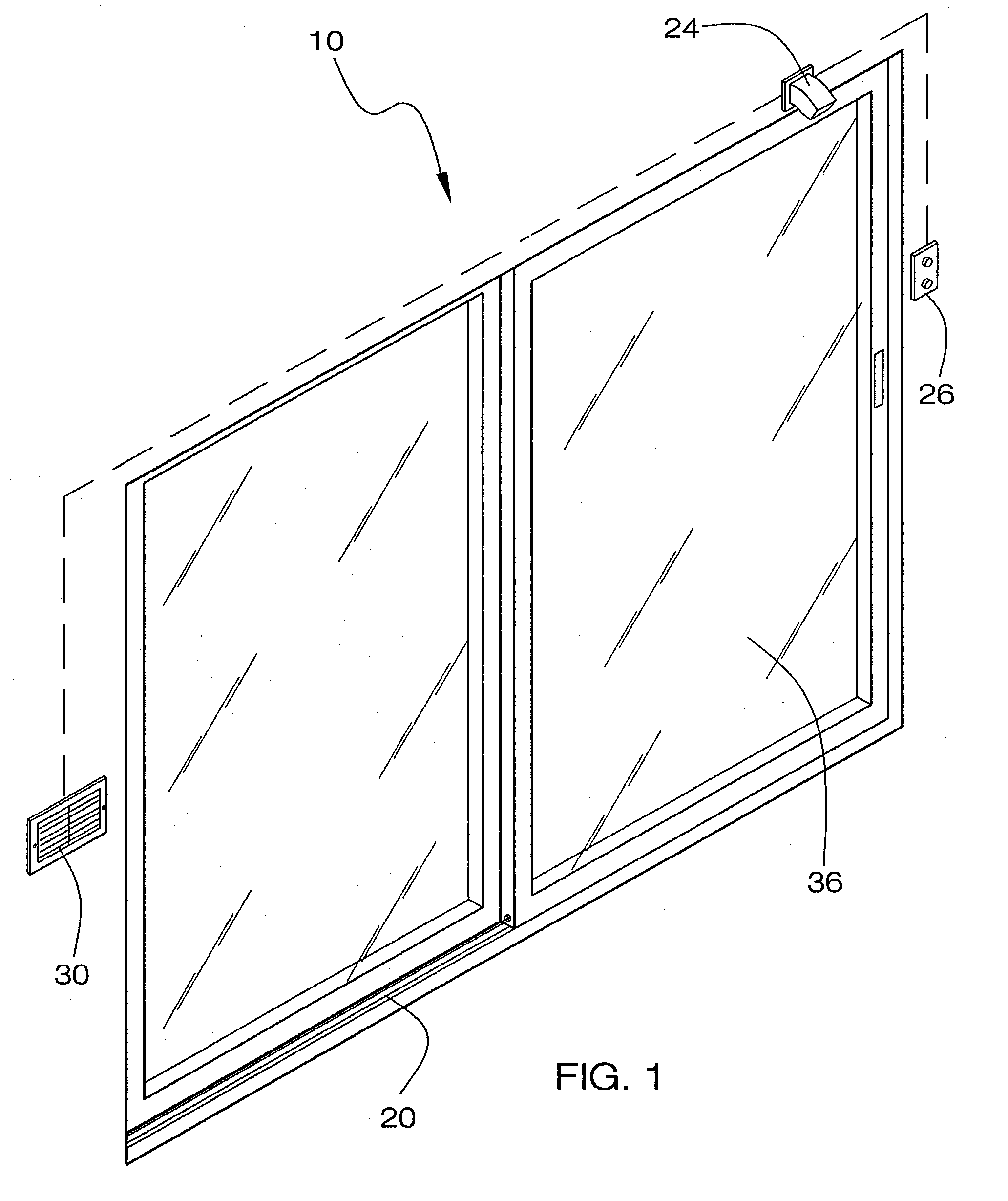
[0027]Referring now to the drawings, and particularly to FIGS. 1–4, a preferred embodiment of the sliding door actuator of the present invention is shown and generally designated by the reference numeral 10.

[0028]In FIG. 1, a new and improved sliding door actuator 10 of the present invention for actuators for sliding doors that have a drive belt and a return spring located within the stud space is illustrated and will be described. A lower drive cable 20 is connected to a sliding door 36. An exit sensor 24 is electrically connected to a drive motor 12 (shown in FIG. 2) to selectively actuate the sliding door 36. A control panel 26 is electrically connected to the drive motor 12 for selectively actuating the drive motor 12. The control panel 26 is capable of receiving wireless control signals. A motor access vent 30 is disposed on the wall directly adjacent to the drive motor 12.

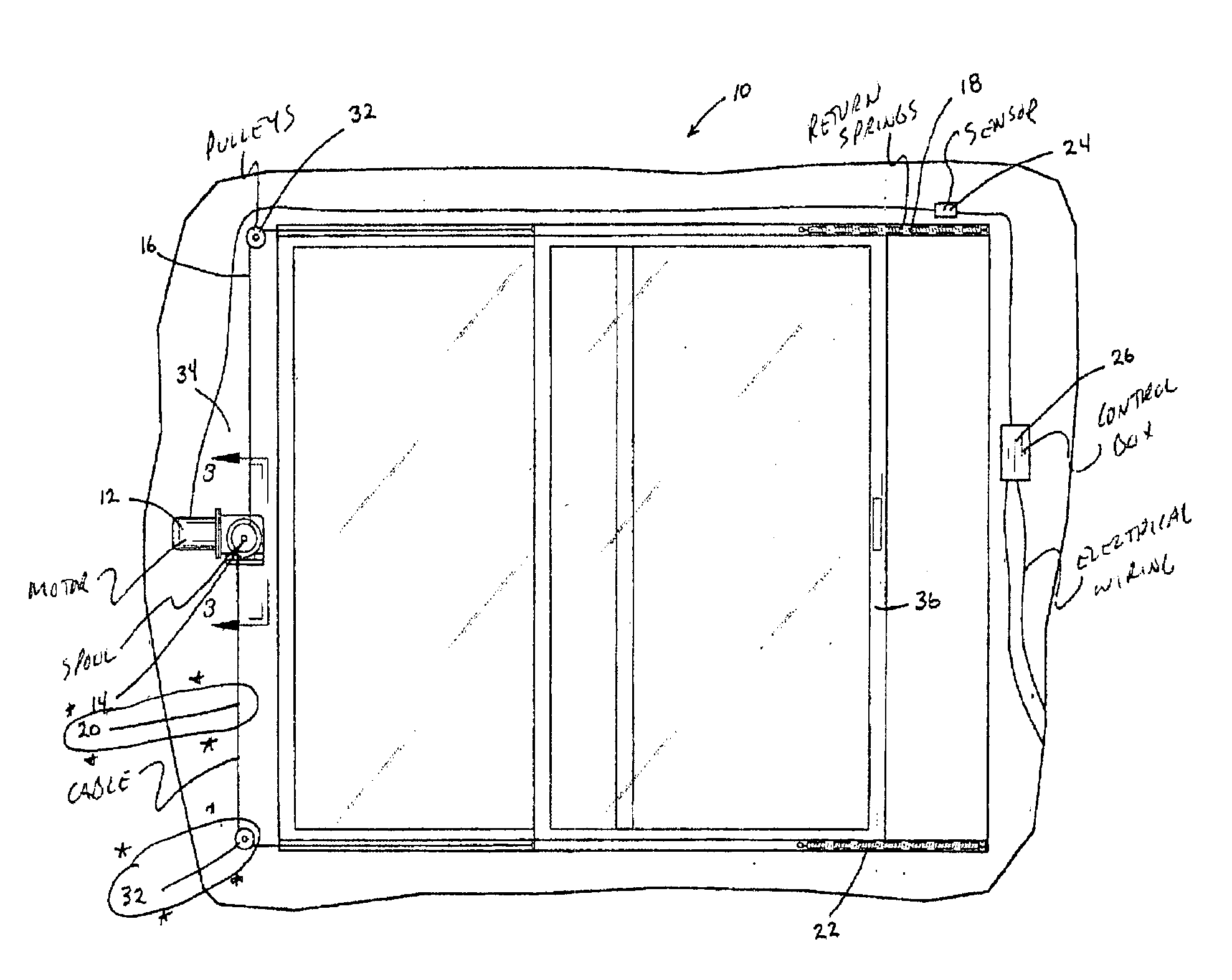
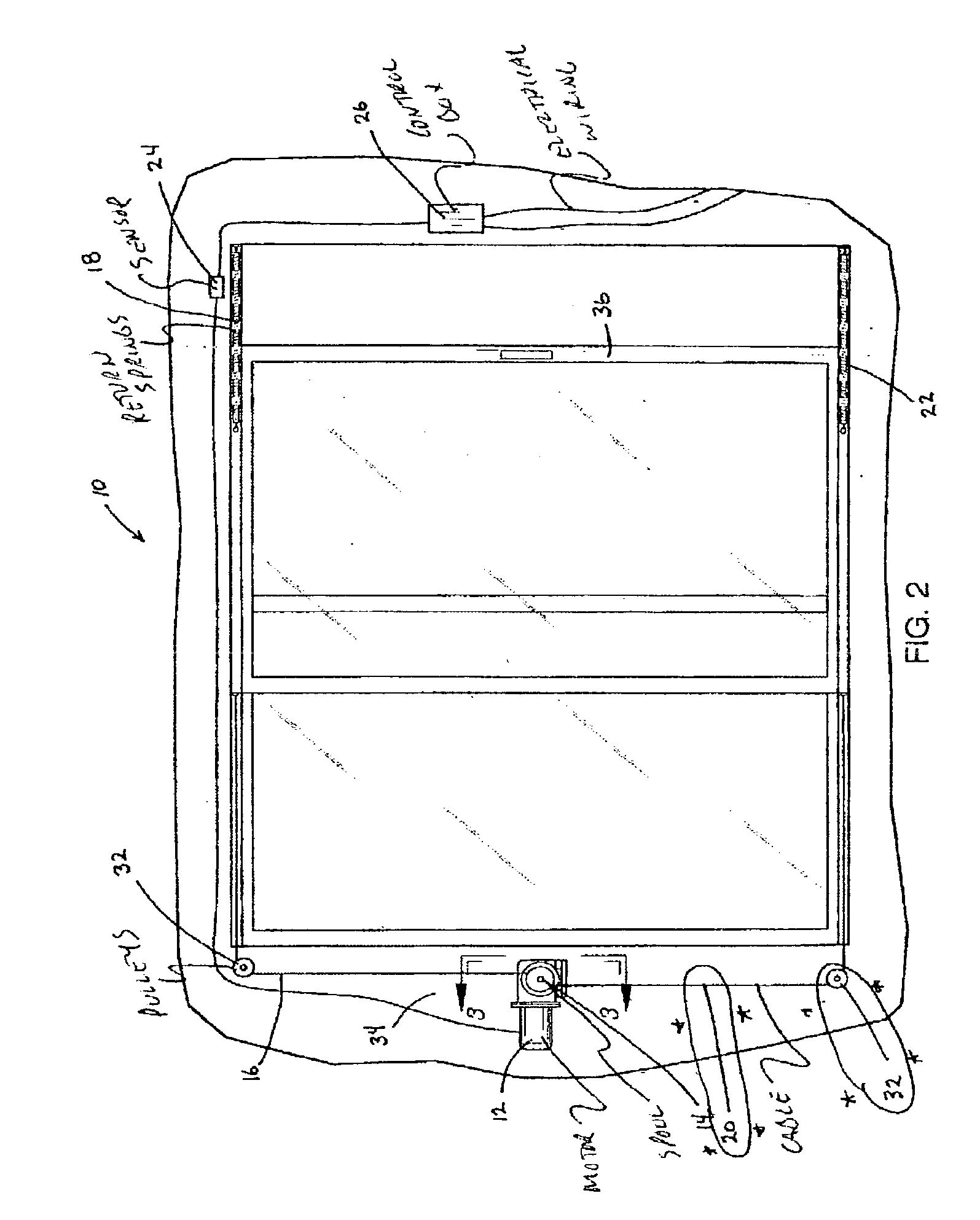
[0029]In FIG. 2, the sliding door actuator 10 is illustrated and will be described. More particularly, the...


PUM


Abstract

A sliding door actuator having a small electric motor and cable system is added to a standard sliding glass door for a residence. As the motor may be controlled by a remote, an individual could simply press a button to open the door. This convenience would be especially helpful to older individuals and those having limited mobility. The sliding door actuator having a winch spool drivingly connected to the drive motor. A drive cable is spoolably connected to the winch spool. The drive cable is connected to a sliding door. A return spring is connected to the drive cable for biasing the sliding door. An exit sensor is electrically connected to the drive motor to selectively actuate the sliding door.

Description

BACKGROUND OF THE INVENTION[0001]1. Field of the Invention[0002]The present invention relates to a sliding door actuator for use in connection with sliding doors. The sliding door actuator has particular utility in connection with actuators for sliding doors that have a drive belt and a return spring located within the stud space.[0003]2. Description of the Prior Art[0004]Sliding door actuators are desirable opening sliding doors for the elderly, handicapped or someone seeking additional convenience by the assistance of a powered device to open the sliding door.[0005]The use of sliding doors is known in the prior art. For example, U.S. Pat. No. 5,656,898 to Kalina discloses a sliding door apparatus that includes a chain driven assembly, a reversible motor for moving the chain and a sliding door driver which converts the chain motion to door movement. A remote control device can also be used to operate the sliding door remotely, especially if users are elderly or handicapped individu...

Claims


Application Information

Patent Timeline
IPC IPC(8): E05F11/00E05F11/54E05F15/14
CPCE05F15/643
Inventor SMILEY, EDWARD D.
Owner SMILEY EDWARD D
Why Eureka
Try Eureka