Multi-zone blanket arrangement

a blanket arrangement and multi-zone technology, applied in the field of electric blankets, can solve the problems of insufficient versatility for multiple users, and inability to achieve the desired temperature setting. achieve the effect of discharging alternate heat levels

a blanket arrangement and multi-zone technology, applied in the field of electric blankets, can solve the problems of insufficient versatility for multiple users, and inability to achieve the desired temperature setting. achieve the effect of discharging alternate heat levels

US7566846B1Inactive Publication Date: 2009-07-28SORENSEN CYNTHIA +1

Image

  • Multi-zone blanket arrangement
  • Multi-zone blanket arrangement
  • Multi-zone blanket arrangement

Examples


Embodiment Construction

[0032]The present invention will now be described more fully hereinafter with reference to the accompanying drawings, in which a preferred embodiment of the invention is shown. This invention may, however, be embodied in many different forms and should not be construed as limited to the embodiment set forth herein. Rather, this embodiment is provided so that this application will be thorough and complete, and will fully convey the true scope of the invention to those skilled in the art. Like numbers refer to like elements throughout the figures.

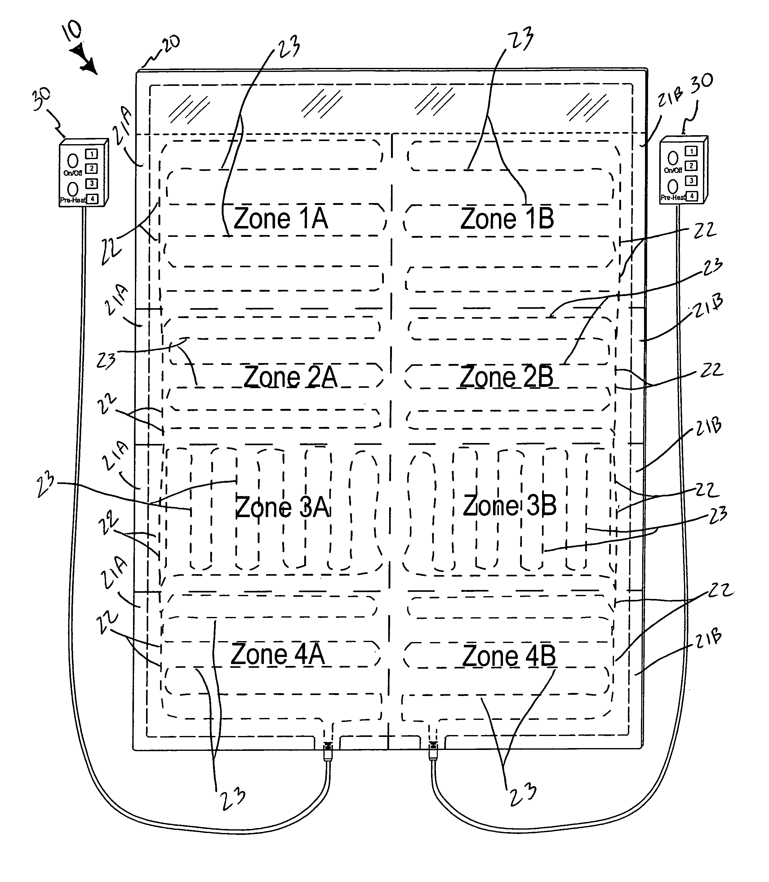
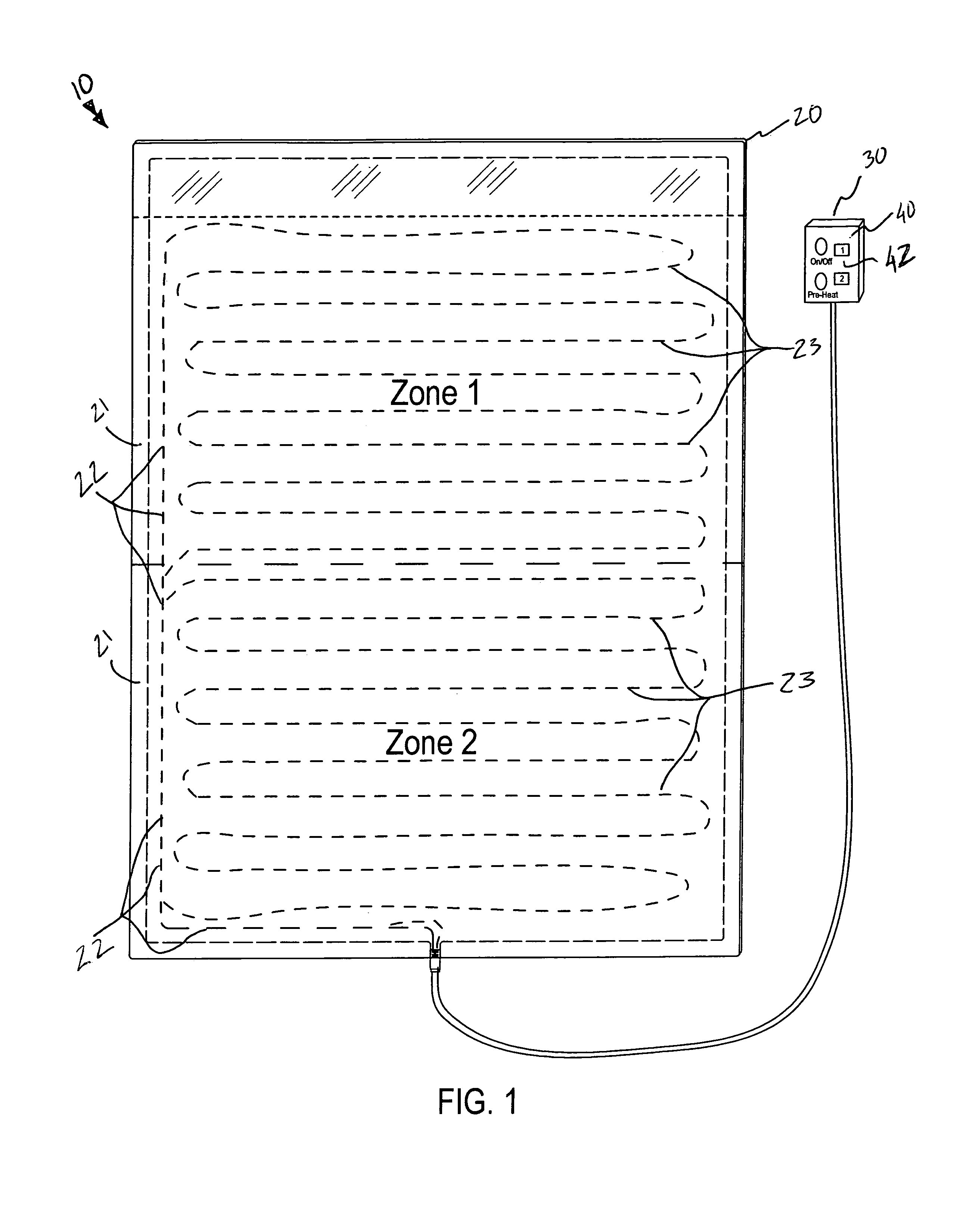
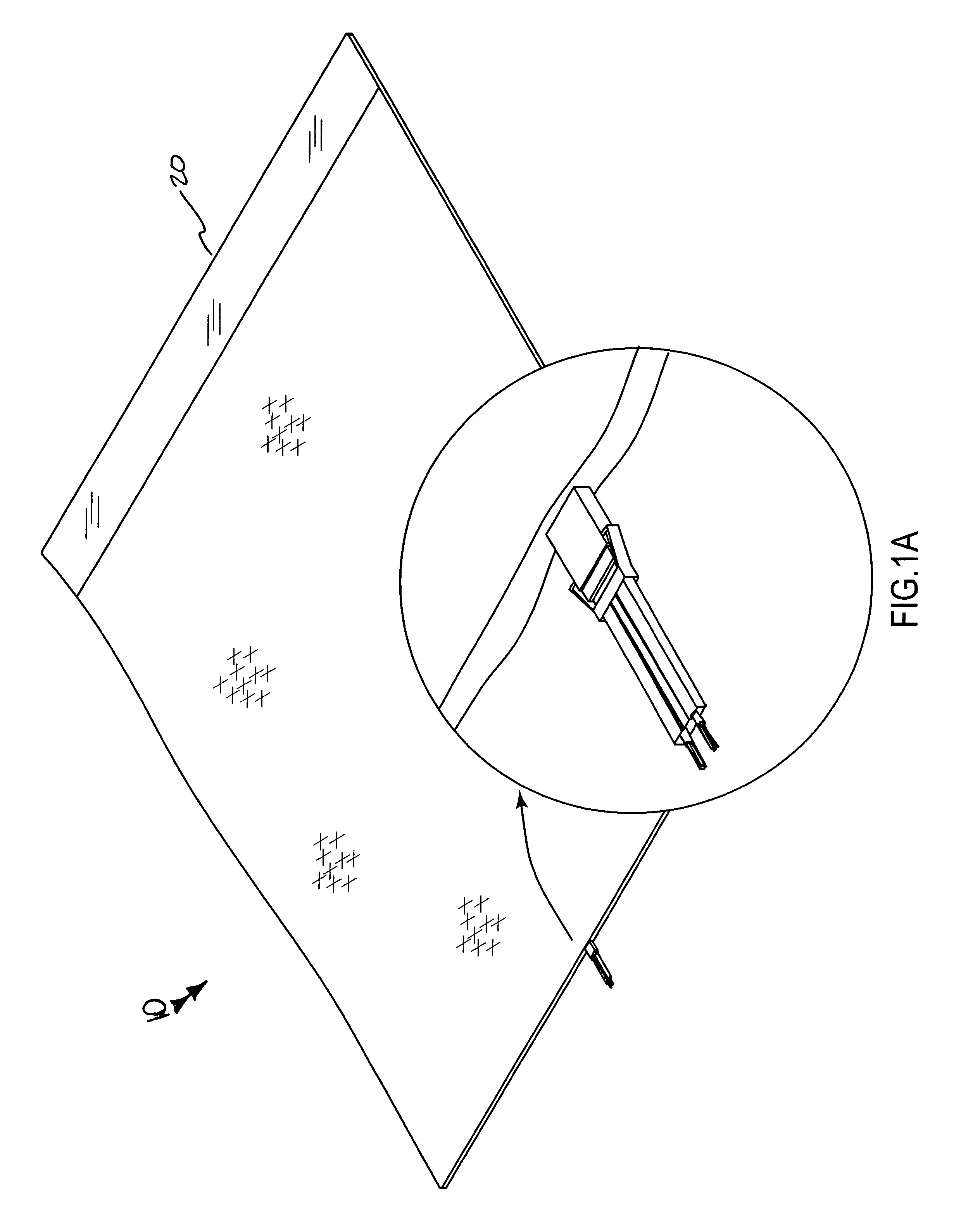
[0033]The device of this invention is referred to generally in FIGS. 1-7 by the reference numeral 10 and is intended to provide a multi-zone blanket arrangement. It should be understood that the device 10 may be used to heat many different types of surfaces and should not be limited in use to only blankets.

[0034]Initially referring to FIGS. 1A, 2 and 5, the device 10 includes a body 20 including a first plurality of heat zones 21A juxtaposed ...


PUM


Abstract

A multi-zone blanket includes a body including first heat zones juxtaposed side-by-side and symmetrically aligned within a body cavity. A first primary heating element passes through each of the first heat zones. A first external controller has an AC / DC transformer electrically coupled thereto. The first controller is electrically coupled and removably attached to the first primary heating element. The transformer is removably coupled to an external power supply source which provides a high voltage input to the transformer. The transformer converts the high voltage input to a low voltage input. The first controller includes a mechanism for providing output control signals to the first heat zones such that each first heat zone can simultaneously and independently generate a selected quantity of heat.

Description

CROSS REFERENCE TO RELATED APPLICATIONS[0001]Not Applicable.STATEMENT REGARDING FEDERALLY SPONSORED RESEARCH OR DEVELOPMENT[0002]Not Applicable.REFERENCE TO A MICROFICHE APPENDIX[0003]Not Applicable.BACKGROUND OF THE INVENTION[0004]1. Technical Field[0005]This invention relates to electric blankets and, more particularly, to a multi-zone electric blanket arrangement for distributing alternate levels of heat for a user.[0006]2. Prior Art[0007]Heating pads and electric blankets are appliances that, by their nature, conduct high current electrical power in close proximity to the user. Known electrically heated pads or blankets are arranged to be heated substantially uniformly over the area of the pad or blanket when the electric heating element is energized. It is also known to provide temperature adjusting means in conjunction with electric blankets for allowing a user to select a setting where the generated heat is comfortable to their liking. This is highly effective in instances wh...

Claims


Application Information

Patent Timeline
28 Jul 2009
Publication
US7566846B1
IPC
H05B1/02
CPC
H05B1/02; H05B3/342; H05B2203/003; H05B2203/005; Y10S2/905
Inventors
SORENSEN, CYNTHIA; SORENSEN, BRIAN