
Color correction of multiple colors using a calibrated technique

Inactive Publication Date: 2009-08-04
APTINA IMAGING CORP
View PDF19 Cites 19 Cited by
  • Summary
  • Abstract
  • Description
  • Claims
  • Application Information

AI Technical Summary

Benefits of technology

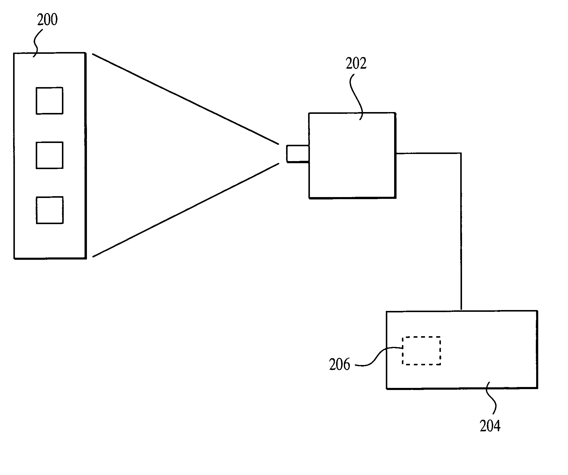
[0013]The present system corrects the signal for all of a plurality of desired colors. Thi

Problems solved by technology

This is complicated, however, by the fact that one only has control over red, green, and blue.

Method used


Image

  • Color correction of multiple colors using a calibrated technique
  • Color correction of multiple colors using a calibrated technique
  • Color correction of multiple colors using a calibrated technique

Examples


Embodiment Construction

[0021]The conventional techniques to determine the coefficients Kij of the color correction matrix are based on analyzing the image of color calibration chart with N distinct color elements. In order to calculate a color correction matrix from the image of the color calibration chart, the appropriate stimuli Yi, suitable for driving a given image rendering device, must be known for each element of the chart from an independent experiment. Such color measurement techniques are, for example, specified by the Commission on Illumination (CIE). Each of N distinct elements of the calibration color chart Yi are known. Xi are determined based on imaging of the chart. The coefficients of the color correction matrix solve N2 linear equations or solve N equations for each chart element.

[0022]Color correction matrix obtained by this technique provides for correction of color rendition of all N colors used in the process, provided that the colors could be physically displayed by the image render...


PUM


Abstract

A system of correcting for color filter array by correcting for a plurality of colors in the color filter array. A color correction matrix is formed which corrects each color for a plurality of desired characteristics simultaneously. These desired characteristics can include, for example, all 24 colors in a chromaticity chart. An additional aspect includes weighting the more important colors relative to the less important colors.

Description

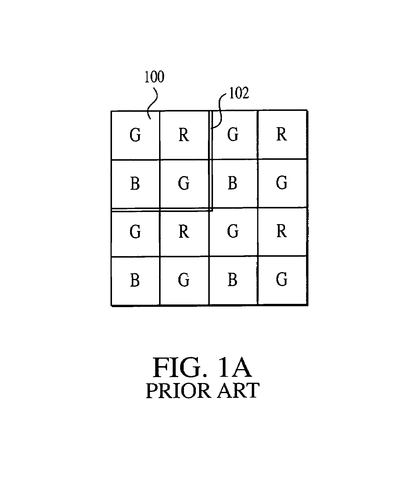
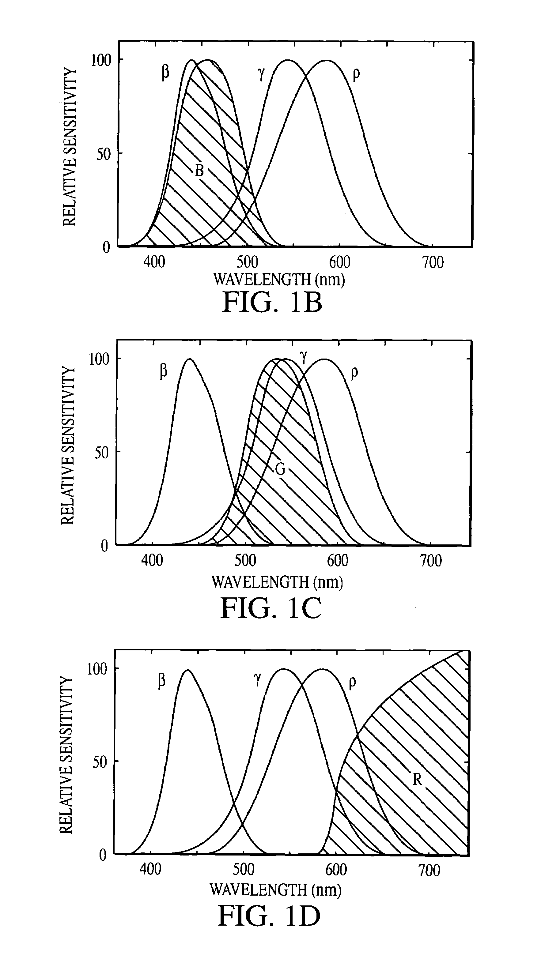
BACKGROUND[0001]A typical color camera separately monitors red, green, and blue components of an image. Electronic imagers rely on some means of separation of the illumination incident on the sensor into a number of spectral channels. Widely-used means of discrimination between spectral components of the imaging scene include the Color Filter Arrays (usually employed in systems based on single focal plane array) and beam-splitting prisms (primarily employed in systems based on multiple focal plane arrays). In either case, the incident illumination is separated into a small number, usually 3 or 4, discrete color (spectral) channels.[0002]For any given scene, the exact ratio of color channel values will depend on the spectral characteristics of the entire optical stage of the imager. This is typically done using a color filter array over a photosensitive area. The color filter array is formed of a plurality of different colored elements, which respectively pass only color of a predete...

Claims


Application Information

Patent Timeline
IPC IPC(8): H04N17/02G06K9/00H04N1/46H04N9/43
CPCH04N1/6033H04N17/02H04N17/002H04N9/67H04N23/85
Inventor KAPLINSKY, MICHAEL
Owner APTINA IMAGING CORP
Learn More