Image processing device, image processing method, image processing system, program, storage medium, and integrated circuit

a technology of image processing and image processing method, applied in image enhancement, image analysis, instruments, etc., can solve the problems of large dependence, increased costs of special devices, weak edge enhancement, etc., and achieve the effect of natural depth in processed images

Inactive Publication Date: 2009-01-22
SOVEREIGN PEAK VENTURES LLC
View PDF13 Cites 74 Cited by
  • Summary
  • Abstract
  • Description
  • Claims
  • Application Information

AI Technical Summary

Benefits of technology

[0066]Through this, it is possible to achieve an integrated circuit that achieves the same effects as the first aspect of the present invention.
[0067]According to the present invention, it is possible to achieve an image processing device, image processing method, image processing system, program, storage medium, and integrated circuit capable of realizing a more natural feeling of depth in processed images by linking correction gain control based on the distance from a vanishing point with the interest level / level of attention directed within the image by a human, and without using differential signal-based border extraction as per the conventional art.

Problems solved by technology

Three-dimensional televisions and the like that utilize the binocular parallax of humans have been proposed in response to this demand, but it has been pointed out that special dedicated glasses are often required, that there is a large degree of dependence on the image, and that the special devices that are required increase costs.
Therefore, even if, for example, the border portions belong to the same object and the object is at the same distance as other objects, there is nevertheless a danger that areas where edge enhancement is stronger and weaker will arise, as well as a danger that areas of discontinuous luminance will arise due to only strong and weak edge emphasis being carried out on border portions.
It also cannot be determined whether a low second order differential luminance signal is caused by issues such as blurriness caused by the photographic conditions (focus point shifting or movement and so on) of the image, interpolation executed during a simple upcoversion from a low-resolution image into a high-resolution image, and so on, or if it is caused by the pixel actually being in the background region.
For this reason, when, for example, an image encoded using a lossy encoding scheme is decoded and distortion within the decoded image is eliminated using a low-pass filter or the like, there is a danger of the entire image being determined as being the background, due to the settings used for determining the value of the threshold of the second order differential signal, which can result in an inability to appropriately carry out the original edge enhancement process.
Furthermore, with pseudo three-dimensional image forming devices and pseudo three-dimensional image forming methods such as those described in Non-Patent Document 1 and Patent Document 2, it is difficult to automatically determine vanishing points for various different types of images.
Furthermore, there is a significant chance that a perspective-based structure, based on a vanishing point, cannot create a three-dimensional image that appears natural to the human eye for all inputted scenes.

Method used


Image

  • Image processing device, image processing method, image processing system, program, storage medium, and integrated circuit
  • Image processing device, image processing method, image processing system, program, storage medium, and integrated circuit
  • Image processing device, image processing method, image processing system, program, storage medium, and integrated circuit

Examples


first embodiment

[0126]An image processing method and an image processing device, which estimate a degree of depth based on an interest level and the distance from a vanishing point and carry out pixel value correction, shall be described as a first embodiment of the present invention, with reference to FIGS. 1 through 12.

[0127]

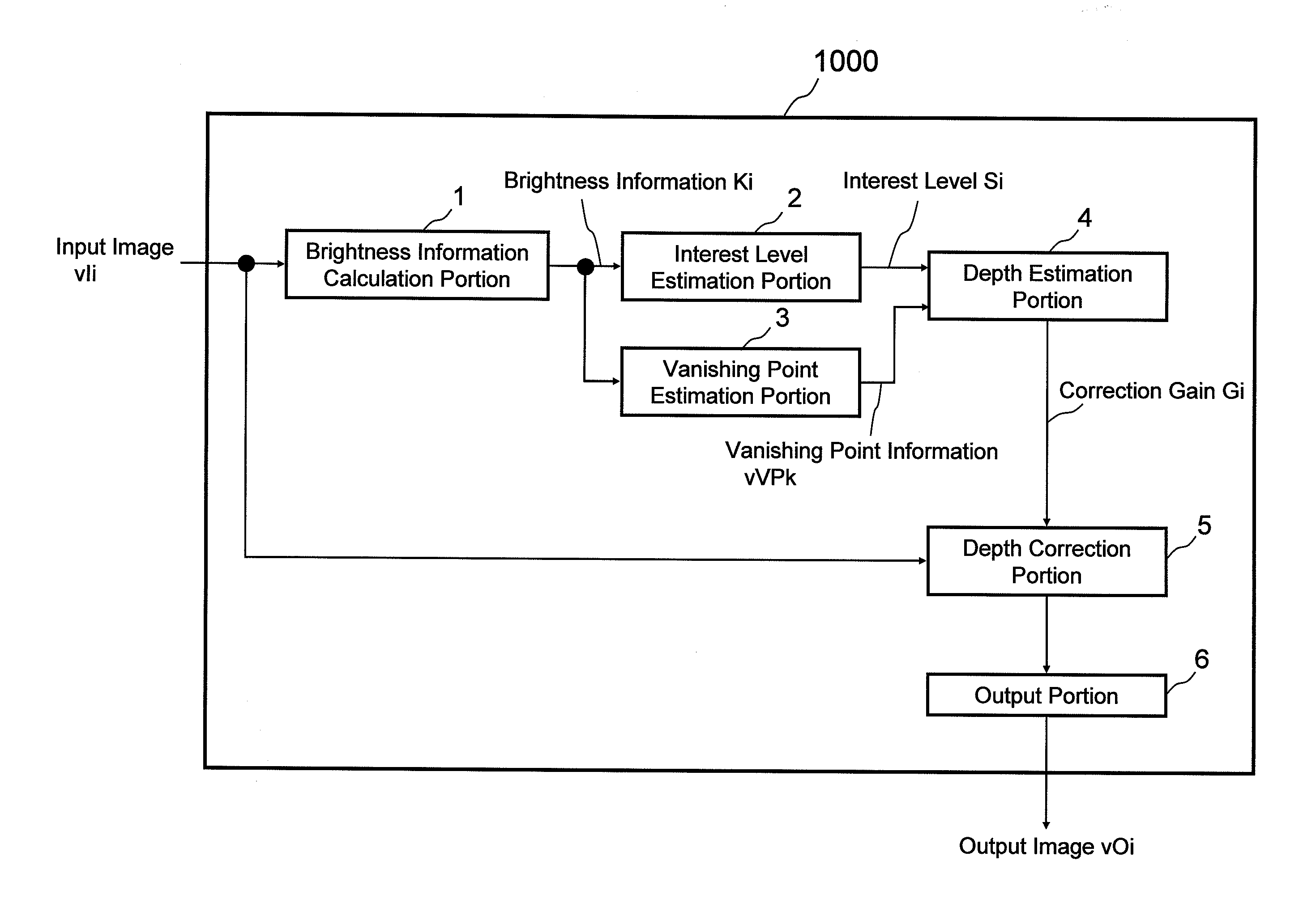
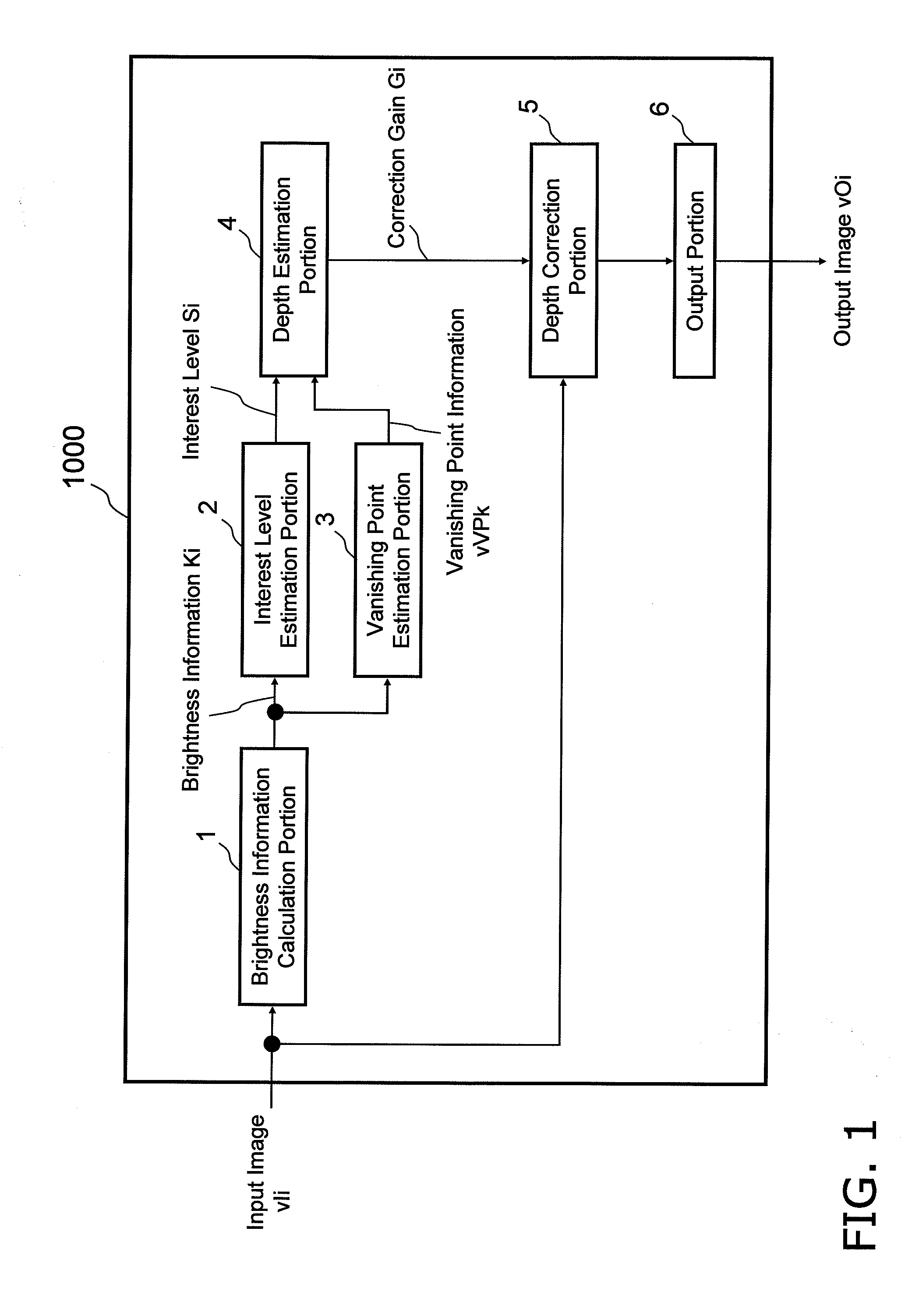
[0128]FIG. 1 is a block diagram illustrating the configuration of an image processing device 1000 according to the first embodiment of the present invention.

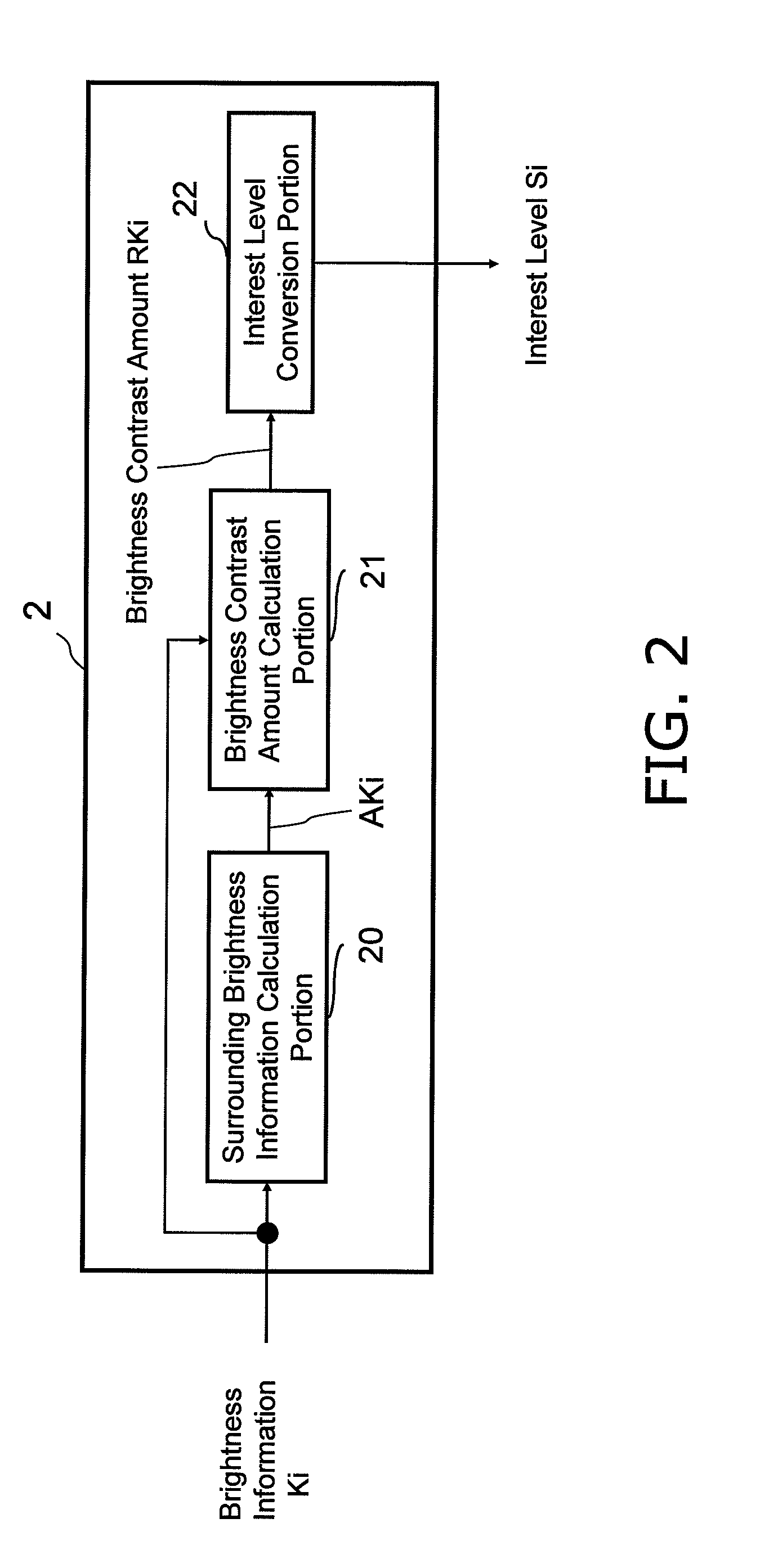
[0129]The image processing device 1000 includes: a brightness information calculation portion 1 that calculates brightness information Ki based on an input image signal vIi; an interest level estimation portion 2 that estimates an interest level Si based on the brightness information Ki; and a vanishing point estimation portion 3 that estimates vanishing point information vVPk based on the brightness information Ki. The image processing device 1000 further includes: a depth estimation portion 4 that estimates a degree of ...

second embodiment

[0225]An image processing method and an image processing device, which estimate a degree of depth based on an interest level and the distance from a vanishing point and carry out pixel value correction, shall be described as a second embodiment of the present invention, with reference to FIGS. 14 through 21.

[0226]

[0227]FIG. 14 is a block diagram illustrating the configuration of an image processing device 2000 according to the second embodiment of the present invention. As shown in FIG. 14, the image processing device 2000 according to the second embodiment differs from the image processing device 1000 according to the first embodiment in that a color information calculation portion 100 has been added and the interest level estimation portion 2 has been replaced with a high-interest level estimation portion 102.

[0228]It should be noted that with the image processing device 2000 according to the present embodiment, portions that are the same as those of the previous embodiment shall ...

third embodiment

[0280]An image processing method and an image processing device, which estimate a degree of depth based on an interest level and the distance from a vanishing point and carry out pixel value correction, shall be described as a third embodiment of the present invention, with reference to FIGS. 22 through 26.

[0281]

[0282]FIG. 22 illustrates the configuration of an image processing device 3000 according to the third embodiment of the invention. As shown in FIG. 22, the image processing device 3000 according to the third embodiment differs from the image processing device 2000 according to the second embodiment in that a frequency component calculation portion 140 has been added and the high-interest level estimation portion 102 has been replaced with an expanded interest level estimation portion 142.

[0283]It should be noted that with the image processing device 3000 according to the present embodiment, portions that are the same as those of the previous embodiment shall be assigned the ...


PUM


Abstract

The present invention executes color correction that improves the feeling of depth of a 2D image with ease and by using a preexisting device.
Input image data is first converted into brightness information by a brightness information calculation portion. The interest level within the image is then estimated by an interest level estimation portion based on that information. The vanishing point is then estimated by a vanishing point estimation portion. Next, a depth estimation portion estimates the degree of depth based on the distance from the vanishing point to a pixel i and the interest level of the pixel i, and calculates a depth correction gain value. A corrected image, obtained by controlling a depth correction image process based on the depth correction gain value, is converted to a predetermined image format and outputted by an output portion. Accordingly, by linking an interest level based on the brightness contrast/color contrast/blurriness amount with the depth estimation based on the vanishing point, the occurrence of abnormalities felt with images that do not properly match up with the perspective structure of the vanishing point, images that do not match the visual impression of humans, and so on can be reduced, making it possible to achieve a more natural and improved feeling of depth.

Description

BACKGROUND OF THE INVENTION[0001]1. Field of the Invention[0002]The present invention relates to image processing methods, image processing devices, image processing programs, and integrated circuits including the stated image processing devices for enhancing the feeling of depth and the three-dimensional effect of a two-dimensional image based on the foreground and background regions of the image.[0003]2. Description of the Related Art[0004]There has been a strong call by users for technology that increases the “feeling of depth” and the “three-dimensional effect” of displayed images in order to display more natural images on the screen of, for example, a large-screen FPD (flat panel display) device. Three-dimensional televisions and the like that utilize the binocular parallax of humans have been proposed in response to this demand, but it has been pointed out that special dedicated glasses are often required, that there is a large degree of dependence on the image, and that the s...

Claims


Application Information

Patent Timeline
Patent Type & Authority Applications(United States)
IPC IPC(8): G06K9/00G06K9/40G06V10/48
CPCG06K9/4633G06T5/001G06T7/0053G06T2207/10024G06T2207/20012G06T2207/20144G06T7/0061G06T7/507G06T7/536G06T7/194G06V10/48
Inventor WATANABE, TATSUMIOJIMA, SHUICHI
Owner SOVEREIGN PEAK VENTURES LLC
Why Eureka
Try Eureka