

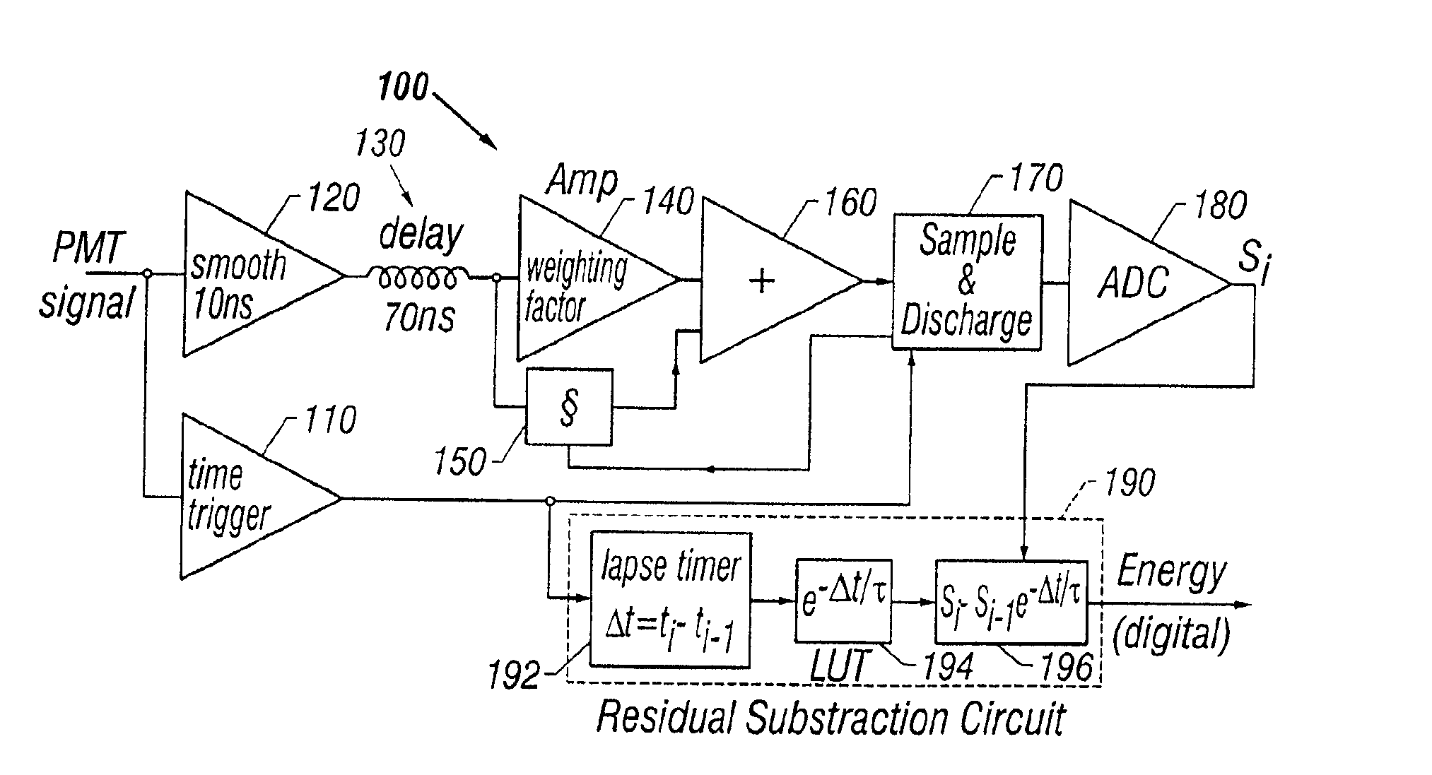
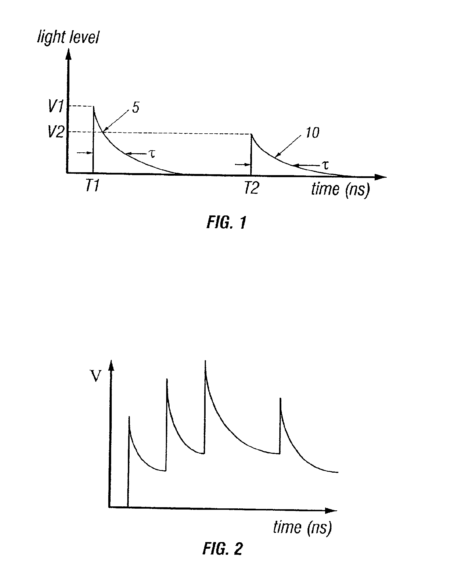
Method and apparatus to prevent signal pile-up
a signal pile and apparatus technology, applied in the field of radiation detection and imaging technology, can solve the problems of affecting the detection system, affecting the detection accuracy of x-rays, etc., and achieves the effects of improving the count-rate capability and dose efficiency of gamma cameras, good timing-resolution, and small dead tim
- Summary
- Abstract
- Description
- Claims
- Application Information
AI Technical Summary
Benefits of technology
Problems solved by technology
Method used
Image

Examples
working examples
[0210]In studies with an exemplary embodiment, the present invention was used in connection with a 3″×4″ NaI(T1) scintillator with a photomultiplier from Ortec Corporation (Oak Ridge, Tenn.). This detector was connected to (1) regular detector electronics setup using a pulse-shaping amplifier (0.5 μs shaping time) and a multi-channel analyzer, and (2) to the pile-up prevention circuit (“PPC”) of the present invention.
[0211]The circuit may be interfaced to a computer. For example, the present invention was connected to a PC computer with a 133 MHz PENTIUM processor and a high-speed input / output board for the studies. The data acquisition software was written with LABVIEW (National Instruments, Austin, Tex.). A 99mTc point source (140 KeV gamma ray) in air was used for all the count-rate studies. The pile-up-prevention circuit of the present invention may also be used to measure the number of nonpile-ups, single pile-ups, and multiple pile-ups.
[0212]For comparison studies, circuits im...
example i
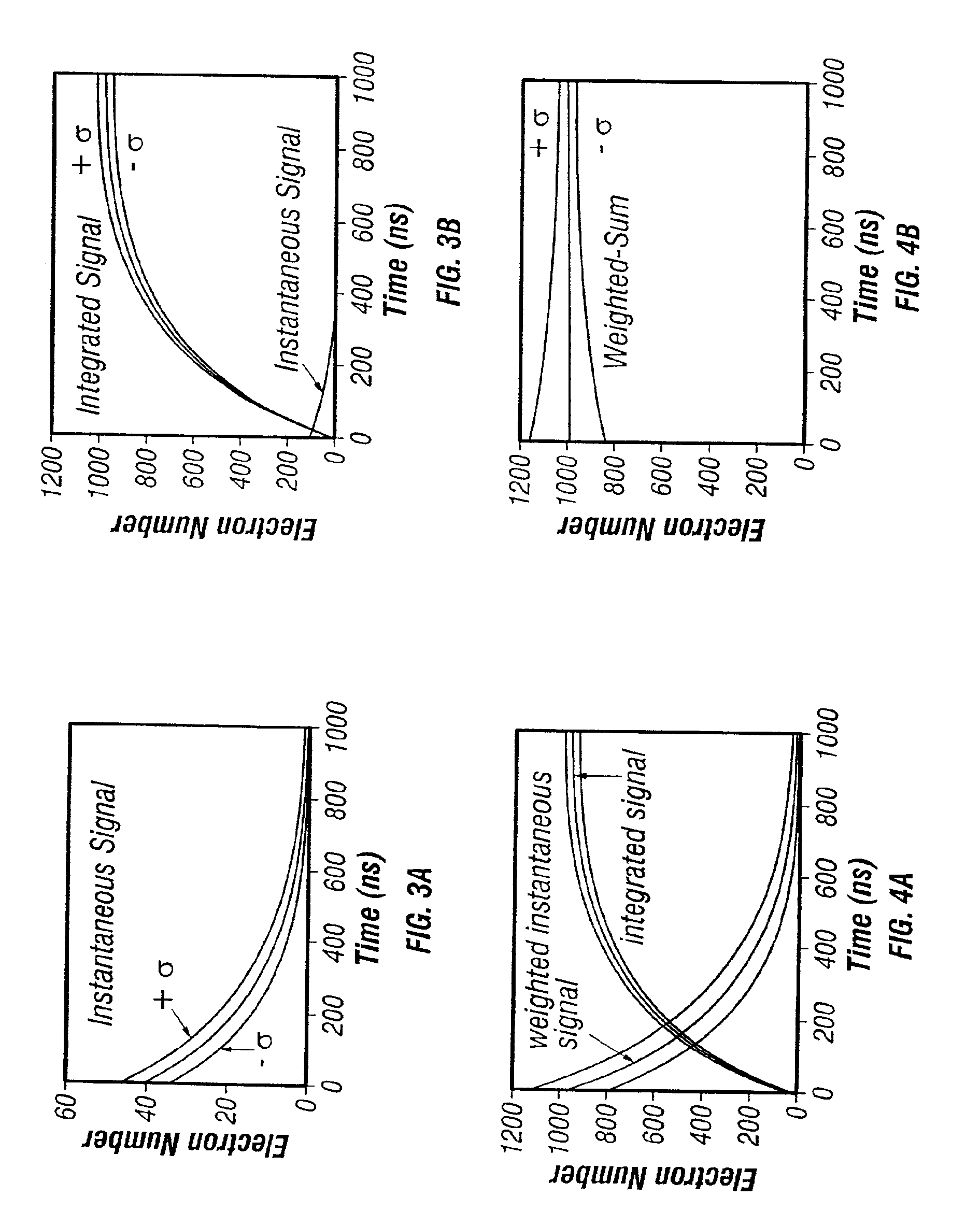
[0213]The pulse height spectra of 99mTc (140 KeV gamma-ray) for the pile-up prevention circuit of the present invention and the pulse-shaping method (500 ns) are shown in FIGS. 12A and 12B. FIG. 12A show results of the pulse-shaping method, and FIG. 12B show results of the present invention. At 50 Kcps, both measured 10.9% energy resolution. At 120 Kcps, the pulse-shaping method (FIG. 12A) started to demonstrate pile-up at the higher energy side and distortion at the lower energy side. Above 200-300 Kcps, the spectra were not usable. The PPC method spectra (FIG. 12B) maintained the spectra shape even at 2 Mcps. This first study demonstrated that the method of the present invention can significantly extend scintillation counting rates. However, the energy resolution was poor at 2 Mcps for this first study. Part of the reason was due to DC-level instabilities because the resistor divider of the photomultiplier (PMT) in the ORTEC probe was AC-coupled and the biasing-current was not des...
example ii
[0214]In a second study, the method of the present invention was compared with a delay-line clipping (DLC) experimental setup (using NIM electronic modules and a 256 ns clipping). The energy resolution results are shown in FIG. 14. At lower count rates, the PPC method had better resolution than the DLC method, while at 2 Mcps the energy resolution was about the same. The study also generated the photopeak-count rates, .i.e. the non-pile-up good counts acquired by each method using a narrow energy window, as a function of true-count rates, as shown in FIG. 15. For the method of the present invention at 2 Mcps, the photopeak counts were 85% of the total incident counts, while the DLC had only 25% good counts. The low photopeak fraction in the DLC method was due to a high 75% count-loss due to pile-ups which placed the pile-up-event energy above the photopeak acceptance-window. The DLC method delayed the occurrence of pile-up due to its shorter pulse width, but at very high count rates...
PUM
 Abstract
Description
Claims
Application Information