

Smart coating systems
a coating system and intelligent technology, applied in the field of multi-layer composite polymer coatings, can solve the problem that the coatings tend to become fouled
- Summary
- Abstract
- Description
- Claims
- Application Information
AI Technical Summary
Problems solved by technology
Method used
Image

Examples
example 1
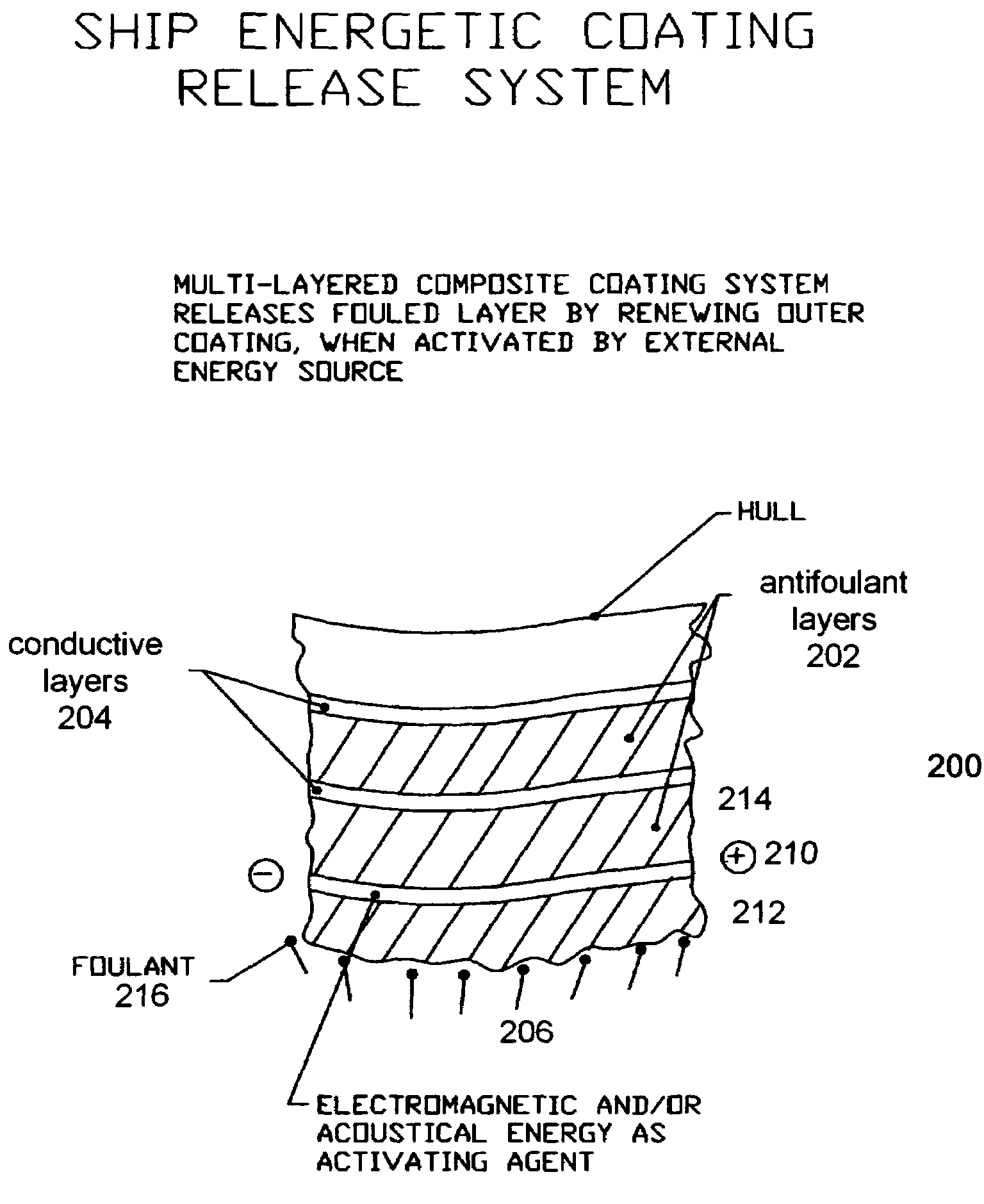
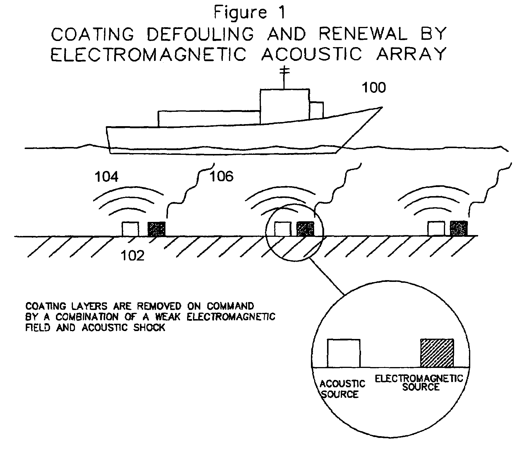
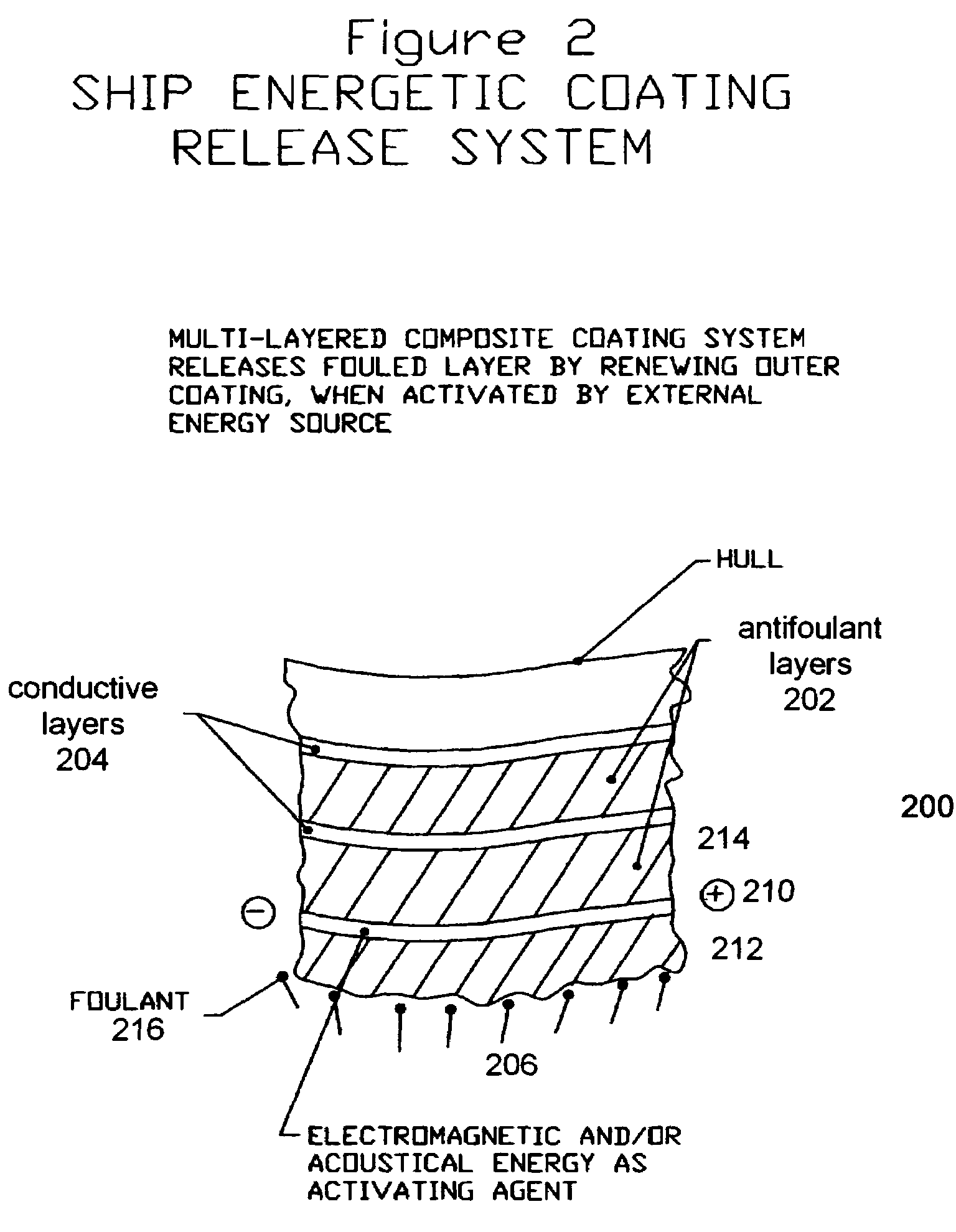
[0018]Systems for use in defouling a ship hull's outer layer and exposing a fresh new surface are shown in FIG. 1 illustrating a ship with external energy activation on it's hull, and FIG. 2 showing the coating. A suitable conductive layer for releasing itself and its adjacent fouled outer antifoulant layer is in the thickness range of ¼ mil to 200 mils. Suitable conductive layer materials include but are not limited to polythiophene, polyfluorene and their derivatives and other conductive conjugated polymers as well as filled polyethylene, polyvinyl chloride, and their derivatives as well as filled polyphenylene sulfide and other water resistant polymers. Conductive fillers include but are not limited to conductive carbon, carbon fibers, and carbon nanotubes, with and without stainless steel coatings, as well as metal flakes or other particle morphologies and other metals including but not limited to copper, or aluminum. Resistivities of the conductive layer materials should be in ...
example 2
[0035]A submarine has been cruising on and off in temperate waters for one year and the captain notices that the boat is using excess fuel and is not handling as well as it should. He orders the chief engineer to check the degree of fouling and he finds that it is at a very high level. The chief engineer then orders his technician to press a defouling button on a maintenance control panel which puts 200 volts DC for 30 seconds across the length of a 20 foot wide by 60 foot long, conductive layer immediately adjacent to a seriously fouled outer antifoulant layer of a coating. The outer antifoulant layer was originally 15 mils thick, but has been reduced to about 5 mils in thickness by wear. The conductive layer then separates from the coating array and exposes the fresh clean smooth surface of the antifoulant layer above it.
[0036]The coating array comprises 5 pairs of conductive layers and antifoulant layers. The array comprises several sections. The sections are 20 feet wide by 60 f...
example 3
[0041]A coast guard cutter has been in operation for two years in cold Canadian Atlantic waters and the second mate determines that there is serious fouling on the hull. As a result, the captain directs that the ship proceed to a cradle in a safe harbor where an operator subjects the conductive layer adjacent to the outer antifoulant layer to a combined electrical / acoustic shock. The outer antifoulant layer and adjacent conductive layer separate from the coating and the clean antifoulant layer above it is exposed.
[0042]The coating is applied in 20 foot wide by 40 foot long sections.
[0043]The antifoulant layers are made of a fluorinated polyurethane polymer and are about 12 mils thick.
[0044]The conductive layers are made of polyphenylene sulfide filled with carbon nanotubes such that the resistivity is 102 ohm-cm. The conductive layers are about 8 mils thick.
[0045]When the cradle operator applies an electrical shock of 150 volts DC for 40 seconds to a conductive layer across the widt...
PUM
| Property | Measurement | Unit |
|---|---|---|
| thickness | aaaaa | aaaaa |
| thickness | aaaaa | aaaaa |
| thickness | aaaaa | aaaaa |
Abstract
Description
Claims
Application Information