Exposure method

a technology applied in the field of exposure apparatus and method, can solve the problems of deteriorating imaging performance, reducing imaging performance, air bubbles likely to occur, etc., and achieve the effect of superior imaging performance and maintaining productivity

Inactive Publication Date: 2007-05-29
CANON KK
View PDF5 Cites 60 Cited by
  • Summary
  • Abstract
  • Description
  • Claims
  • Application Information

AI Technical Summary

Benefits of technology

[0011]Accordingly, the present invention is directed to an exposure method, which keep the air bubbles from a liquid used to the immersion liquid, achieve a superior imaging performance, and maintain the productivity.

Problems solved by technology

It is important for the immersion exposure to keep the liquid away from air bubbles, because they scatter the exposure light and deteriorates the imaging performance.
However, at the time of the initial filling or when the liquid surfaces of the liquid supplied from the liquid supply nozzle are separated although the liquid exists between the final lens surface and the wafer, the liquid surfaces contact each other and the air bubbles likely to occur.
This results in the reduced imaging performance due to the generated air bubbles, and the decreased productivity of semiconductor device manufacture.
This configuration decreases the throughput of the exposure apparatus, and the productivity of semiconductor device manufacture.

Method used


Image

  • Exposure method
  • Exposure method
  • Exposure method

Examples


Embodiment Construction

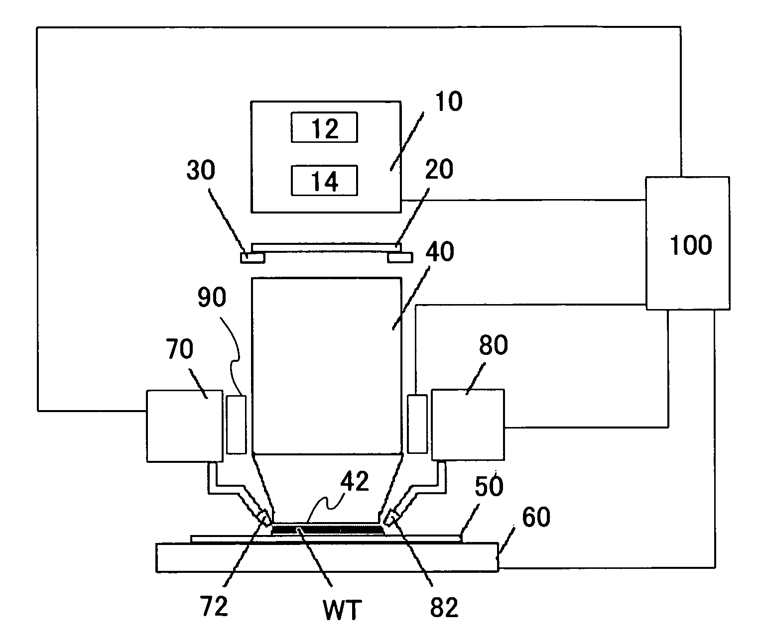
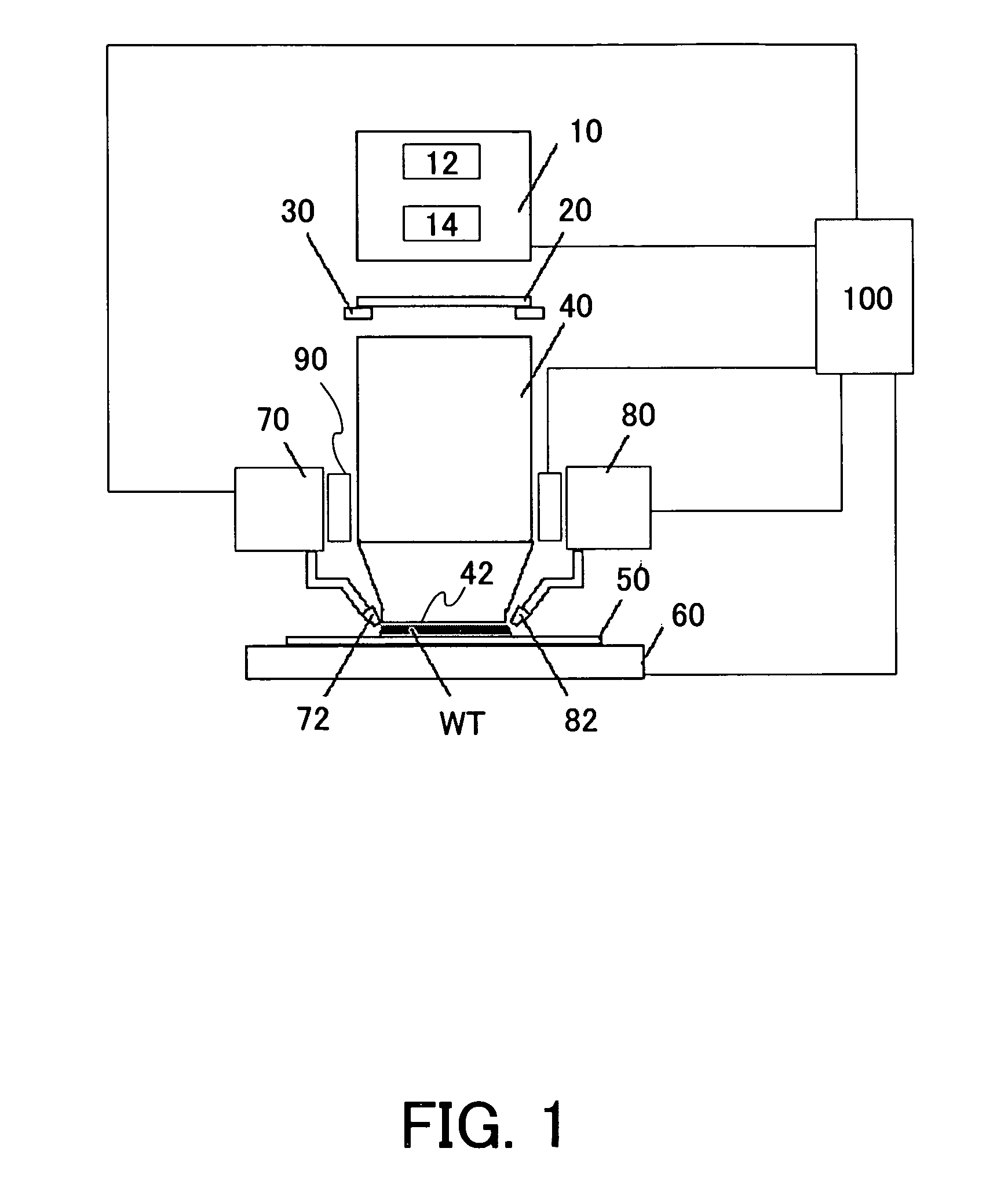
[0023]With reference to the accompanying drawings, a description will be given of an exposure apparatus 1 of one embodiment according to the present invention. In each figure, the same reference numeral denotes the same element. Therefore, duplicate descriptions will be omitted. FIG. 1 is a schematic sectional view of an exposure apparatus 1.

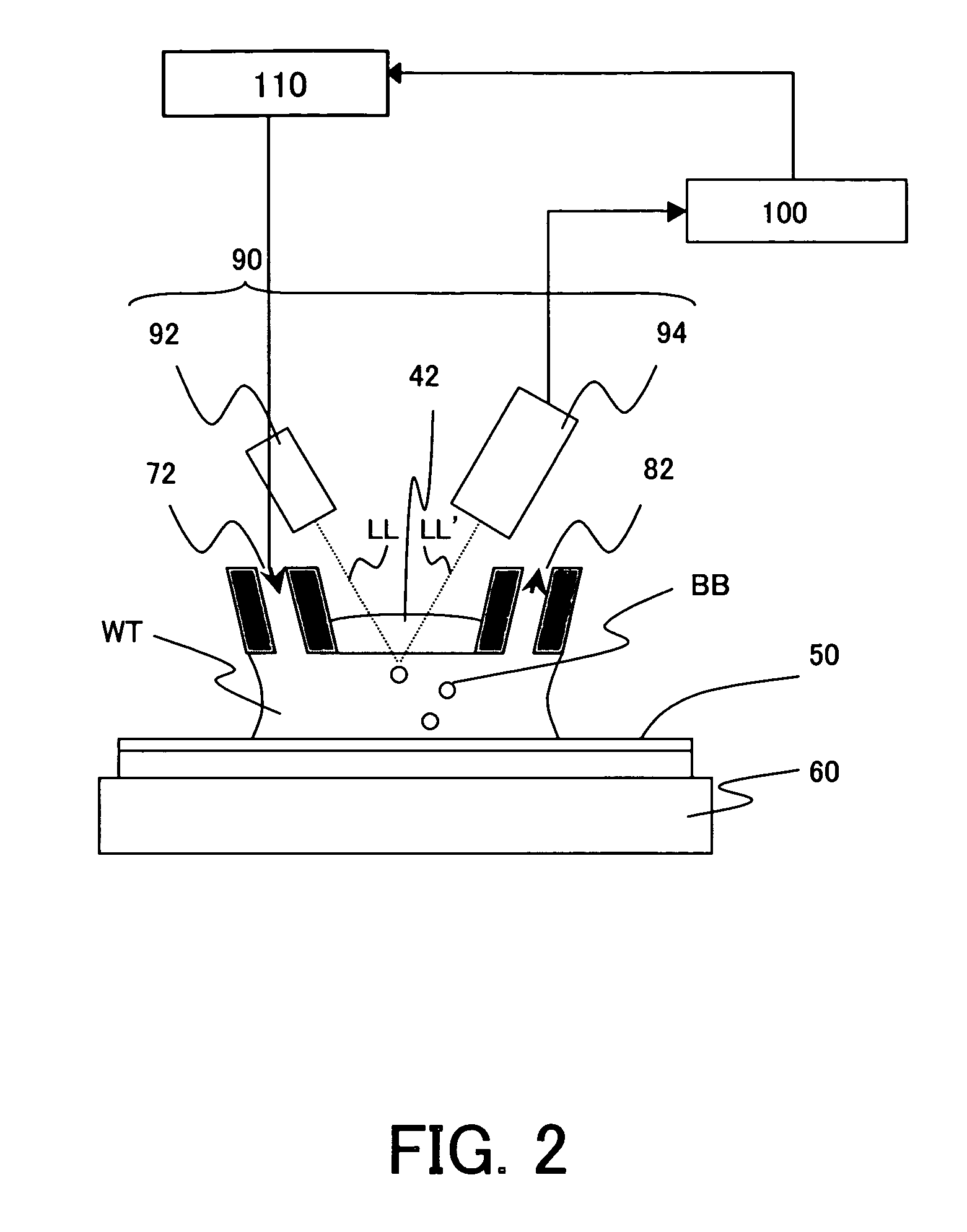
[0024]The exposure apparatus 1 is an immersion exposure apparatus that exposes onto an object 50 a circuit pattern of a reticle 20 via a liquid WT supplied between a final lens surface 42 at the object 50 side of a projection optical system 40. Such an exposure apparatus is suitable for a sub-micron or quarter-micron lithography process. The instant embodiment exemplarily describes a step-and-scan exposure apparatus (which is also called “scanner”). However, the present invention is applicable to step-and-repeat manner. “The step-and-scan manner,” as is used herein, is an exposure method that exposes a reticle pattern onto a wafer by continuousl...


PUM


Abstract

An exposure apparatus includes a projection optical system for projecting a pattern of a reticle onto an object to be exposed, via a liquid that is filled in a space between said projection optical system and the object, and a removing part for removing an air bubble and / or a foreign particle mixed in the liquid by forming a predetermined flow velocity distribution in the liquid.

Description

BACKGROUND OF THE INVENTION[0001]The present invention relates generally to an exposure apparatus and method, and more particularly to an exposure apparatus and method that exposes an object, such as a single crystal substrate of a semiconductor wafer and a glass plate for a liquid crystal display (“LCD”). The present invention is suitable for a so-called immersion exposure apparatus that fills a space with liquid between a final surface of a projection optical system and a surface of an object, and exposes the object via the liquid.[0002]Conventionally, the photolithography technology has employed a reduction projection exposure apparatus using a projection optical system to project a circuit pattern of a reticle (mask) onto a wafer, etc., in manufacturing fine semiconductor devices such as a semiconductor memory and a logic circuit.[0003]The minimum critical dimension to be transferred by the projection exposure apparatus or resolution is proportionate to a wavelength of light use...

Claims


Application Information

Patent Timeline
Patent Type & Authority Patents(United States)
IPC IPC(8): G03B27/42G03B27/32G03B27/52
CPCG03F7/70341
Inventor TOKITA, TOSHINOBU
Owner CANON KK
Why Eureka
Try Eureka