Neutron detectors and related methods

a neutron detector and detector technology, applied in the field of neutron detectors and related methods, can solve the problems of system performance limitations, position resolution, count rate capability, logistic complications, etc., and achieve high spatial resolution imaging capability, high count rate, and high resolution

Active Publication Date: 2008-05-13
RADIATION MONITORING DEVICES
View PDF14 Cites 63 Cited by
  • Summary
  • Abstract
  • Description
  • Claims
  • Application Information

AI Technical Summary

Benefits of technology

[0008]The columns formed by the microcapillaries can vary in length and, in some embodiments, can be made long to enhance detection efficiency without sacrificing spatial resolution. For increased neutron detection efficiency, the microcapillary material, such as glass forming a microcapillary tube, may be doped with special additives which have high thermal neutron cross-section. Devices and assemblies can further include an optically coupled photodetector or high resolution readout to realize high performance neutron detection. Another advantage of the present invention is that the scintillators can be fabricated in a large area with relatively low cost.
[0009]Additionally, the high-performance, high resolution characteristics of the present neutron detecting scintillator devices are advantageously suitable for use in a wide variety of applications, including dynamic studies. For example, the fast decay of the scintillator allows for high count rates (e.g., up to about 100 MHz) and suitability for dynamic studies. The neutron detecting scintillators have time decay constants in the nanosecond range, which is significantly faster than neutron sensitive scintillators used for imaging having time decay constants in the μs-ms range. For example, in one embodiment it is expected that the disclosed scintillator could reach nanosecond response in the range of 1 to 250 ns while providing very high spatial resolution imaging capability. In one embodiment, for example, scintillators of the invention are configured for high spatial resolution imaging, the imaging comprising a spatial resolution with a value less than about 100 μm (e.g., better than about 100 μm), and typically less than about 50 μm (e.g., about 45 μm). Optionally, scintillator compositions can further include additional elements to effect composition characteristics, such as materials that waveshift the emission spectrum of the scintillator composition, for example, so as to select a quantum efficiency to better match optically coupled photodetectors or readouts.
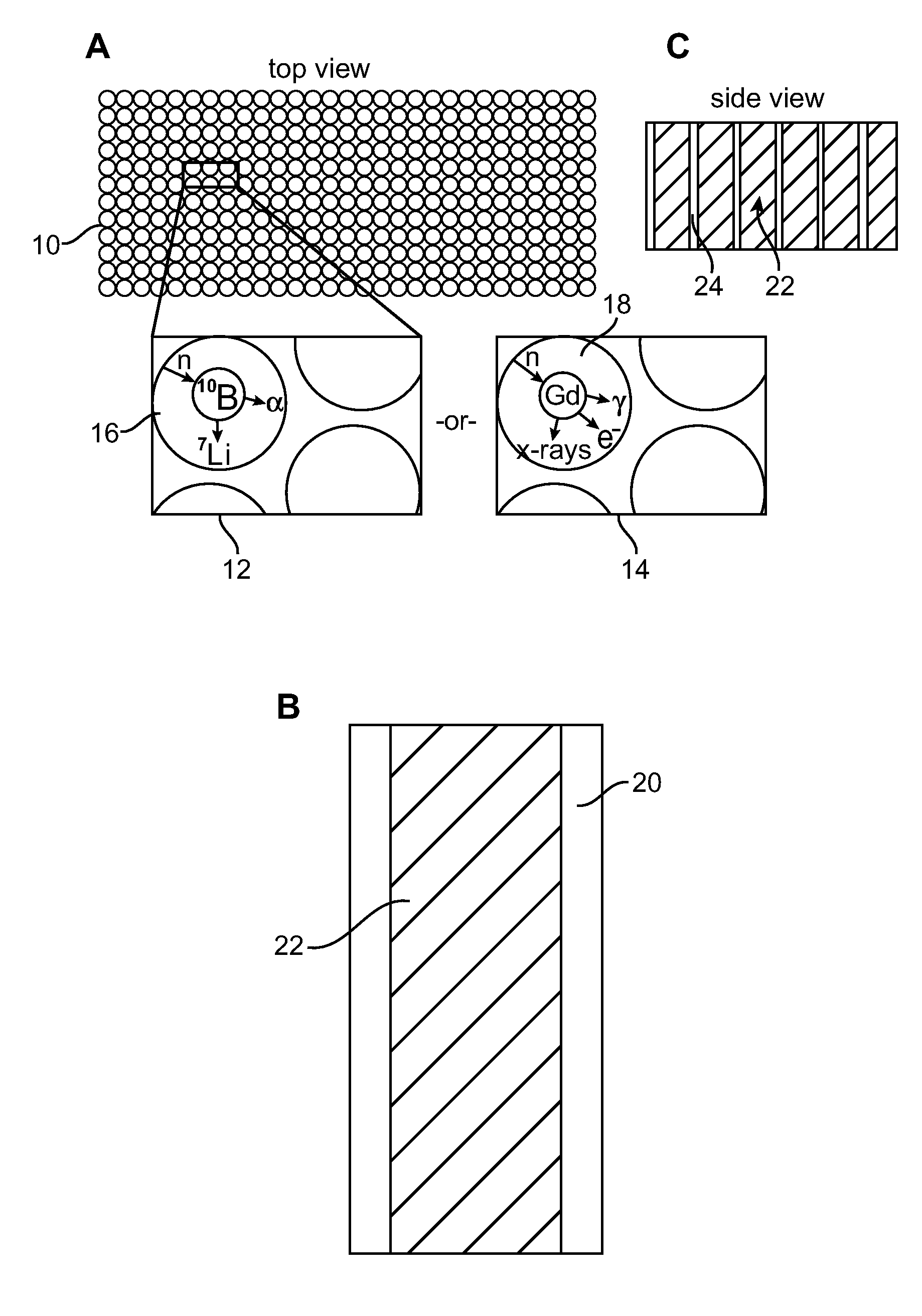
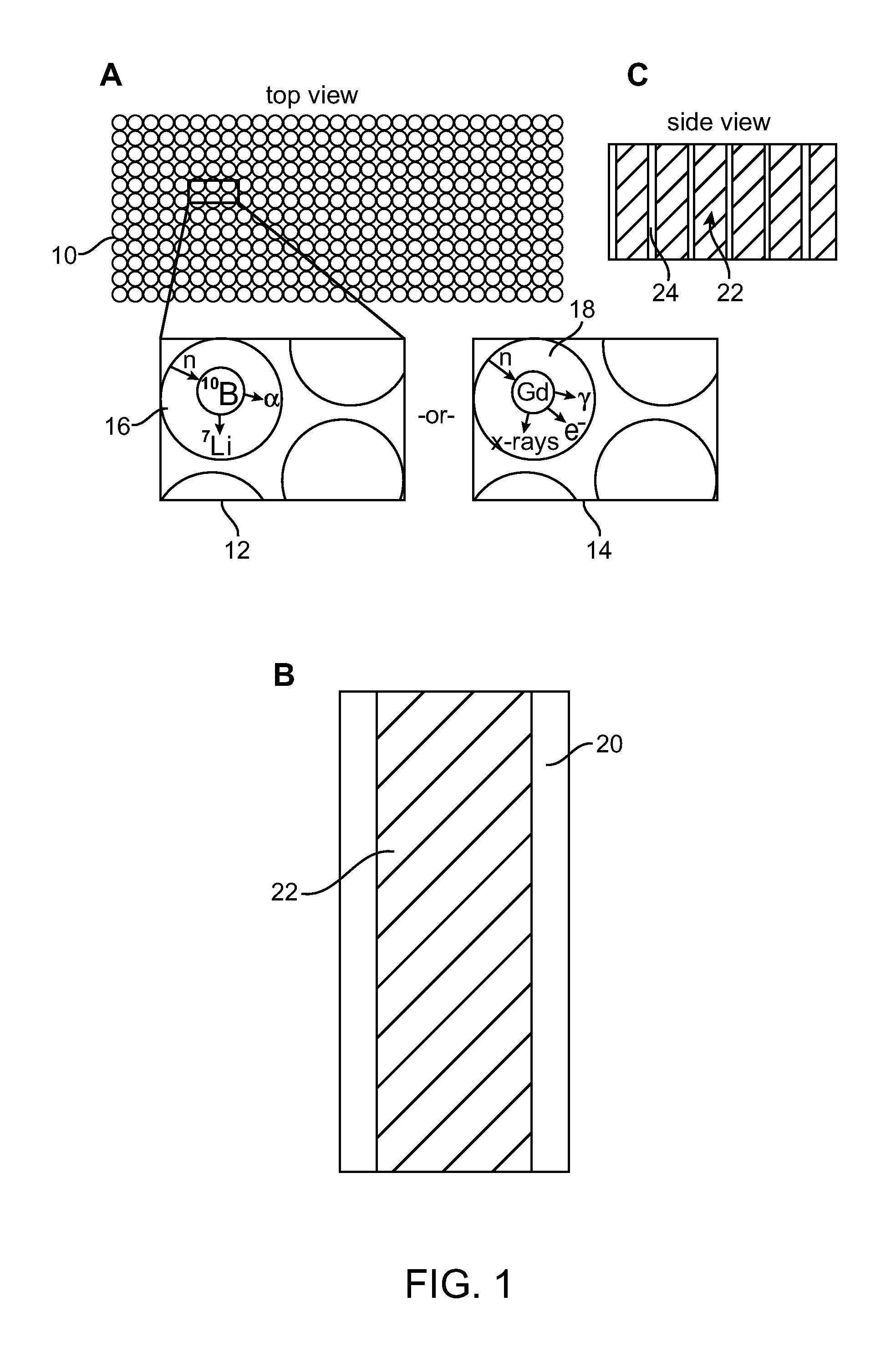
[0010]Thus, in one aspect the present invention includes a neutron detecting scintillator. The neutron detecting scintillator includes a plurality of microcapillary tubes loaded with a scintillator composition comprising a plastic scintillator and a neutron absorbing material. Additionally, the capillary array can be focused toward the radiation source, for example, where the source of neutrons is viewed through a pinhole-collimator, or through a coded aperture mask for applications such as detecting hidden illicit radioactive materials. Thus in one embodiment of the present invention the capillary array of a scintillator, or at least a plurality of capillaries or loaded microcapillary tubes of the scintillator are said to be “focused” or oriented to substantially match a predetermined illumination direction of a radiation beam reaching the pixel.
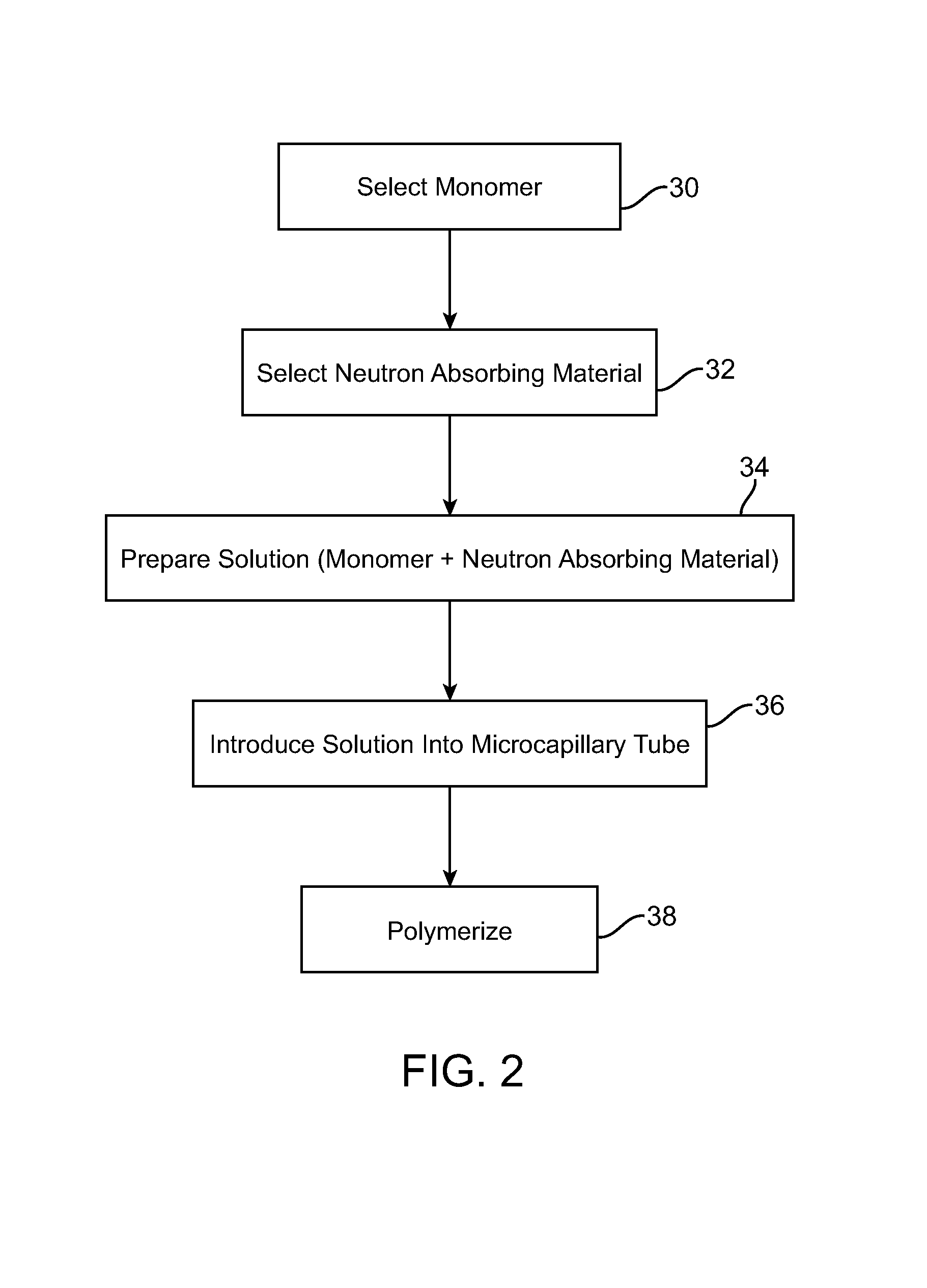
[0011]In another aspect, the present invention provides methods of producing a neutron detecting scintillator having a plurality of microcapillary tubes loaded with a scintillator composition comprising a plastic scintillator and a neutron absorbing material. The method includes preparing a solution comprising a monomer and a neutron absorbing element, introducing the solution into a microcapillary tube of the plurality, and polymerizing the solution within the microcapillary tube.
[0012]The present invention can also make use of tubes having dimensions that are larger in size, which can be manipulated and / or drawn down into microcapillary sized tubes, for example, following introduction of a solution or scintillator composition into the tube. Thus, in yet another aspect of the present invention, a method of producing a neutron detecting scintillator having a plurality of microcapillary tubes loaded with a scintillator composition comprising a plastic scintillator and a neutron absorbing material, such a method includes preparing a solution comprising a monomer and a neutron absorbing element. The method additionally includes introducing the solution into a tube and drawing down the tube to form a microcapillary tube. Following drawing down of the tube, the method includes polymerizing the solution within the microcapillary tube.
[0013]Methods of the invention can include polymerizing a solution disposed within a tube prior to drawing down the tube to form a microcapillary tube. Thus, in one embodiment the present invention provides methods of producing a neutron detecting scintillator having a plurality of microcapillary tubes loaded with a scintillator composition comprising a plastic scintillator and a neutron absorbing material, the method includes preparing a solution comprising a monomer and a neutron absorbing element, introducing the solution into a tube, polymerizing the solution within the tube, and then drawing down the tube to form a microcapillary tube.

Problems solved by technology

Despite advantages and great promise of neutron detection based techniques, the techniques of neutron crystallography and neutron radiology are relatively underutilized compared to other techniques such as x-ray crystallography.
One reason for that is the lack of suitable high performance neutron detectors, such as position sensitive thermal neutron detectors.
All these systems have significant performance limitations in terms of sensitivity, position resolution, count rate capability, logistic complications, or lack of real-time output.
The performance of currently available detectors is thus a factor limiting more wide-spread implementation of neutron detectors, and is due at least partially to the current lack of scintillators suitable for high performance neutron detection.
For example, currently available scintillators with slow response, and low discrimination between neutron and other events, such as gamma-ray events, typically must sacrifice spatial resolution for detection efficiency, thereby further degrading the performance.

Method used


Image

  • Neutron detectors and related methods
  • Neutron detectors and related methods
  • Neutron detectors and related methods

Examples


Embodiment Construction

[0023]Referring to FIGS. 1A through 1C, a neutron detecting scintillator of the present invention is described. FIG. 1A illustrates a top view of a neutron detecting scintillator 10. The scintillator 10 includes a plurality of microcapillary tubes that are loaded with a scintillator composition including a plastic scintillator and a neutron absorbing material. Focused views 12, 14 schematically illustrate interaction of the neutron absorbing material with an incident neutron, and subsequent reaction with the plastic scintillator of the scintillator composition. View 12 illustrates a microcapillary tube 16 loaded with a scintillator composition with neutron absorbing boron. View 14 shows a microcapillary tube 18 loaded with scintillator composition having neutron absorbing gadolinium (Gd). As illustrated, an incident neutron interacts with a neutron absorbing material of the scintillator composition. The energetic photons or particles (e.g., x-rays, gamma rays, alpha particles, etc.)...


PUM


Abstract

The present invention relates generally to neutron detecting scintillators and related methods and devices. A neutron detecting scintillator includes a plurality of microcapillary tubes loaded with a scintillator composition comprising a plastic scintillator and a neutron absorbing material. The present invention additionally provides methods of producing a neutron detecting scintillator having a plurality of microcapillary tubes loaded with a scintillator composition comprising a plastic scintillator and a neutron absorbing material. The method includes preparing a solution comprising a monomer and a neutron absorbing element, introducing the solution into a microcapillary tube of the plurality, and polymerizing the solution within the microcapillary tube.

Description

BACKGROUND OF THE INVENTION[0001]The present invention relates generally to neutron detecting scintillators and devices. More specifically, the present invention relates to neutron detecting scintillators, devices and related methods, a scintillator including a plurality of microcapillary tubes loaded with a scintillator composition including a plastic scintillator and a neutron absorbing material.[0002]Scintillation spectrometers and devices are widely used in detection and spectroscopy of energetic photons and / or particles (e.g., x-rays, gamma-rays, neutrons). Such detectors are commonly used, for example, in nuclear and particle physics research, medical imaging, diffraction, non-destructive testing, nuclear non-proliferation monitoring, and the like.[0003]Scintillators and scintillation based detectors are generally well known. Scintillation spectrometry generally comprises a multi-step scheme. Specifically, scintillators work by converting energetic particles such as x-rays, ga...

Claims


Application Information

Patent Timeline
Patent Type & Authority Patents(United States)
IPC IPC(8): G01T3/06
CPCG01T3/06
Inventor NAGARKAR, VIVEKSHESHTAKOVA, IRINAOVECHKINA, LENA
Owner RADIATION MONITORING DEVICES
Why Eureka
Try Eureka