Helmet cooling and heating system

Inactive Publication Date: 2009-08-11
BIKES EDUARD
View PDF2 Cites 23 Cited by
  • Summary
  • Abstract
  • Description
  • Claims
  • Application Information

AI Technical Summary

Benefits of technology

[0023]It is another object of the present invention to provide a new and improved helmet cooling system which may be easily and efficiently manufactured and marketed.
[0024]It is further object of the present invention to provide a new and improved helmet cooling system which is of durable and reliable constructions.
[0025]An even further object

Problems solved by technology

The helmet is fabricated of a mat

Method used


Image

  • Helmet cooling and heating system
  • Helmet cooling and heating system
  • Helmet cooling and heating system

Examples


Example

[0037]The same reference numerals refer to the same parts throughout the various Figures.

DESCRIPTION OF THE PREFERRED EMBODIMENT

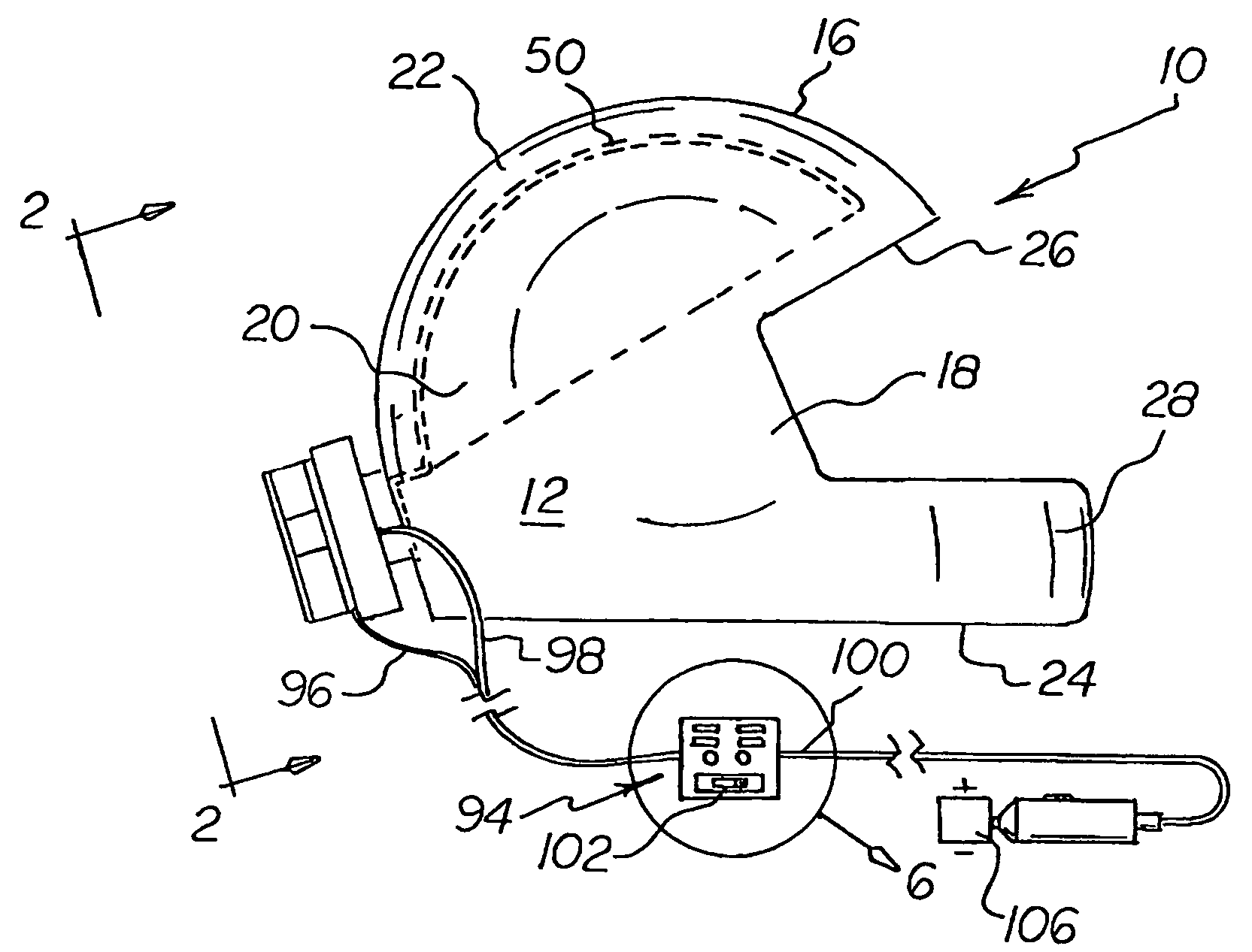
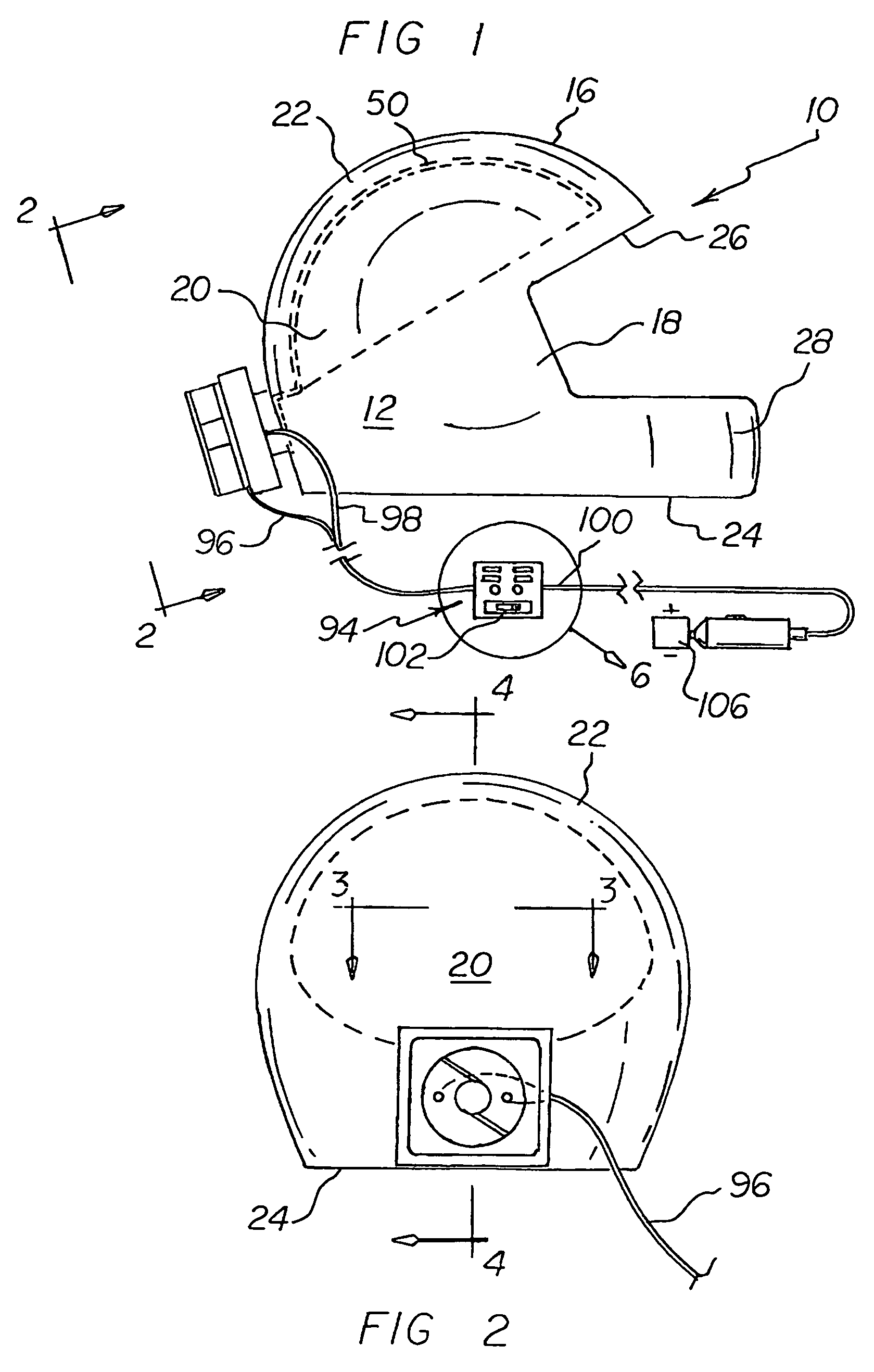
[0038]With reference now to the drawings, and in particular to FIG. 1 thereof, the preferred embodiment of the new and improved helmet cooling system embodying the principles and concepts of the present invention and generally designated by the reference numeral 10 will be described.

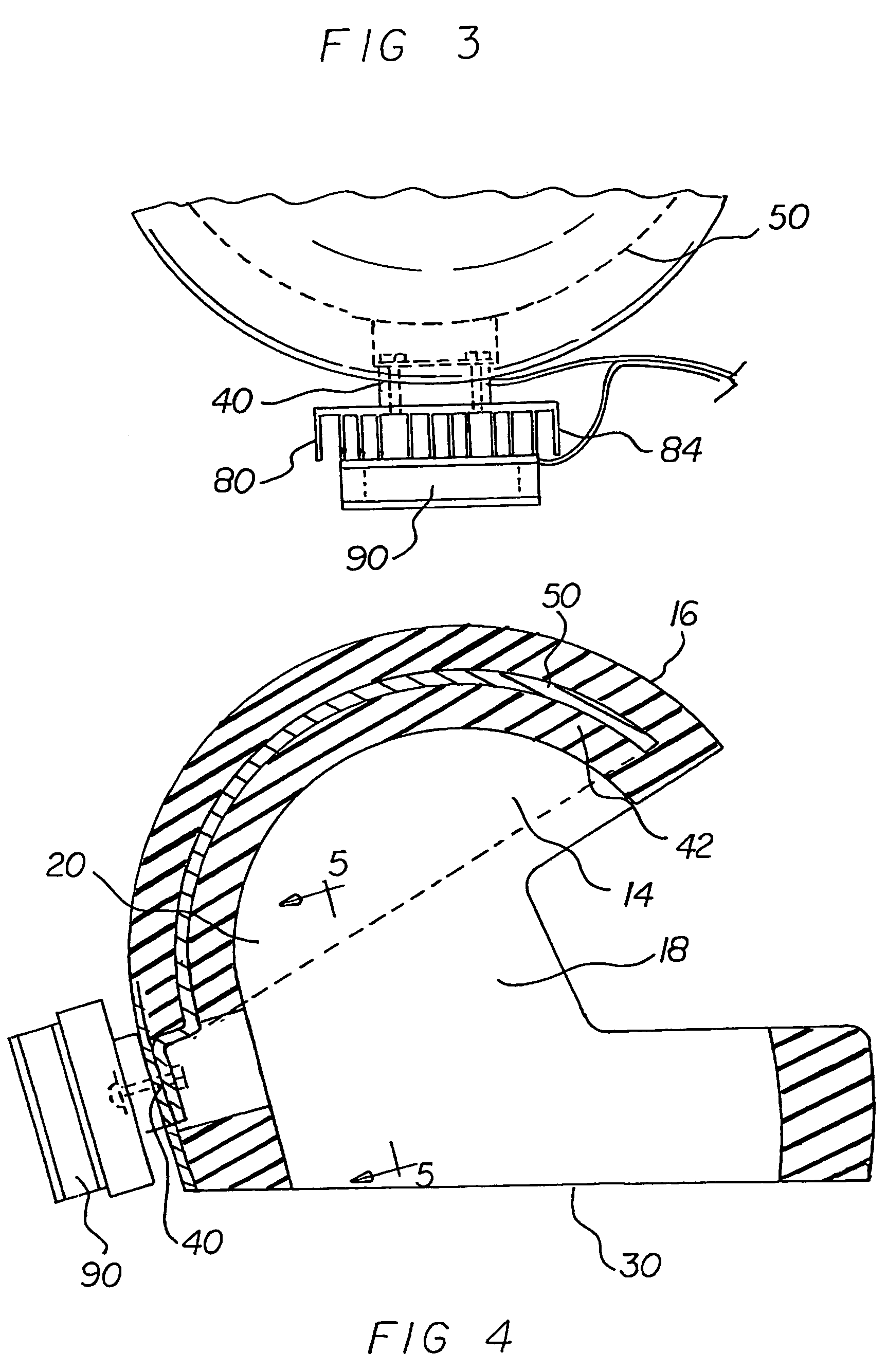
[0039]The present invention, the helmet cooling system 10 is comprised of a plurality of components. Such components in their broadest context include a helmet, a cooling plate, a heat sink and a controller. Such components are individually configured and correlated with respect to each other so as to attain the desired objective.

[0040]A protective gear cooling device, comprising several components, in combination.

[0041]First provided is a helmet 12. The helmet is fabricated of a material having limited flexibility. The material used is a member of a class of materials having li...


PUM


Abstract

A protective gear cooling device, comprising a helmet having an inside surface and an outside surface. There is a cooling plate coupled to the inside surface of the helmet. A pnp conductor and an npn conductor are coupled to the cooling plate. A heat sink is coupled to the conductors and to the outside surface of the helmet. A fan is coupled to the heat sink. A control module is electronically coupled to the fan and the conductors. Power is provided by a direct current power source. The source is electronically coupled to the control module.

Description

BACKGROUND OF THE INVENTION[0001]1. Field of the Invention[0002]The present invention relates to a helmet cooling system and more particularly pertains to a system to cool the inside of a helmet during use.[0003]2. Description of the Prior Art[0004]The use of known devices and apparatuses to cool a helmet is known in the prior art. More specifically, known devices and apparatuses to cool a helmet previously devised and utilized for the purpose of cooling a helmet when in use are known to consist basically of familiar, expected, and obvious structural configurations, notwithstanding the myriad of designs encompassed by the crowded prior art which has been developed for the fulfillment of countless objectives and requirements.[0005]By way of example, U.S. Pat. No. 4,457,135 issued to Hakuraku et al. on Jul. 3, 1984 discloses a magnetic refrigerating apparatus. U.S. Pat. No. 4,509,334 issued to Nakagome et al. on Apr. 9, 1985 discloses a magnetic refrigerator. Lastly, U.S. Pat. No. 4,5...

Claims


Application Information

Patent Timeline
IPC IPC(8): F25B21/02
CPCA42B3/285A42B3/286F25B21/02F25B2321/0251
Inventor BIKES, EDUARD
Owner BIKES EDUARD
Why Eureka
Try Eureka