
System, method, and apparatus for a radially-movable line termination system for a riser string on a drilling rig

a technology of riser string and line termination system, which is applied in the direction of drilling pipes, drilling well accessories, sealing/packing, etc., can solve the problems of small movement, few limitations, and a bit cumbersome to manipula

Inactive Publication Date: 2009-08-11
VETCO GRAY
View PDF20 Cites 30 Cited by
  • Summary
  • Abstract
  • Description
  • Claims
  • Application Information

AI Technical Summary

Benefits of technology

"The present invention is a line termination assembly for use in oil and gas drilling operations. The assembly includes a ring adapter and a ring body that are connected together using lock pins and a key pin. The ring body is discontinuous with the slip joint, allowing for movement in a radial direction during assembly and disassembly. Terminal blocks are mounted to the ring body for connecting choke, kill, and auxiliary lines. The assembly is designed to provide a secure and reliable connection between the riser string and the fluid bearings and tension rings, while also allowing for independent testing of the termination lines. The technical effects of the invention include improved safety and reliability during drilling operations."

Problems solved by technology

The forces generated by these hazards cause significant motion of the rig that must be compensated to maintain the continuity of the riser string that extends down from the rig and is fixed to the ocean floor.
Although conventional KT rings provide numerous advantages they also have a few limitations.
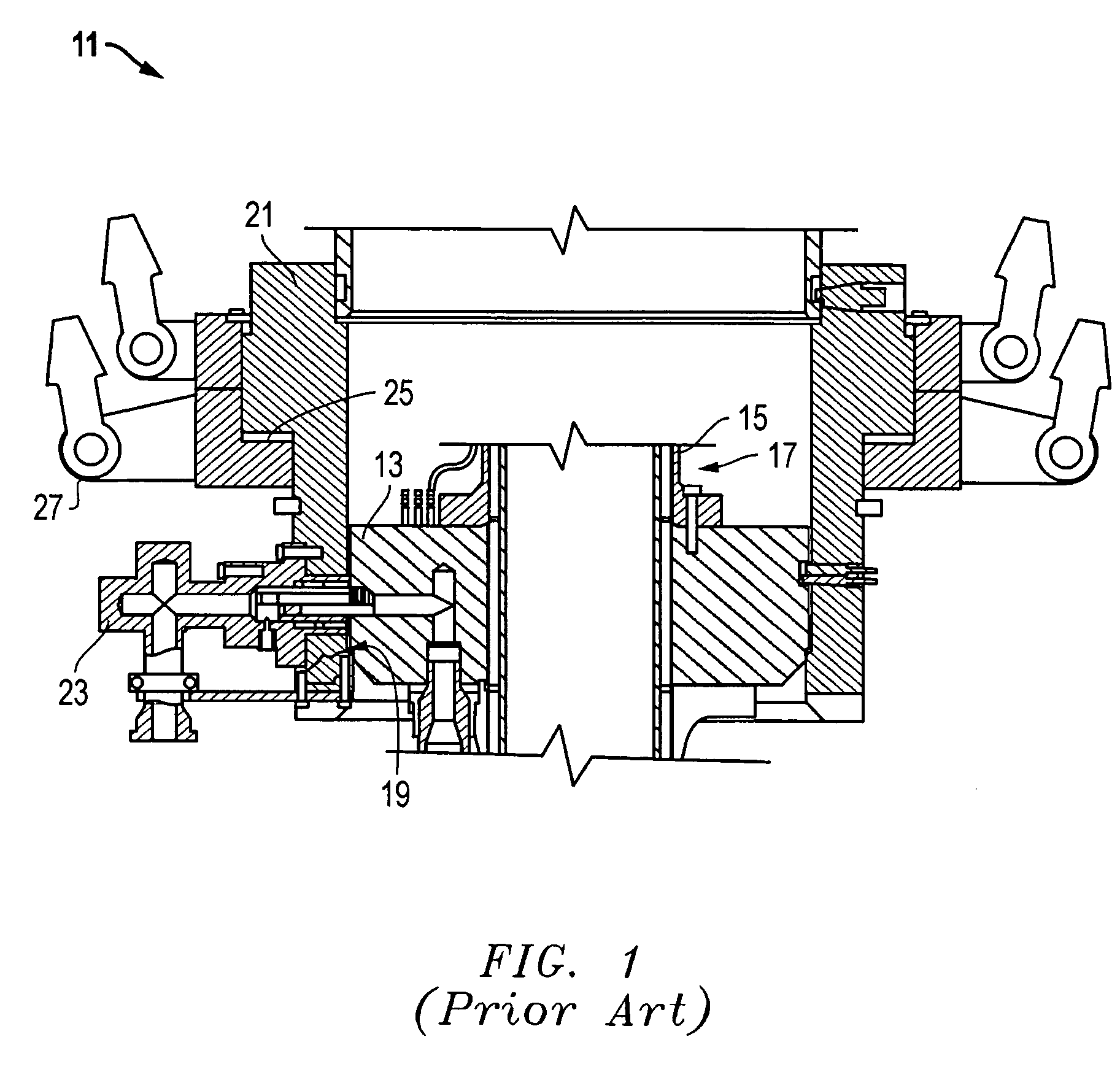
The large size of the ring body makes it somewhat cumbersome to manipulate, and it consumes significant space between the floors of drilling rig.

Method used


Image

  • System, method, and apparatus for a radially-movable line termination system for a riser string on a drilling rig
  • System, method, and apparatus for a radially-movable line termination system for a riser string on a drilling rig
  • System, method, and apparatus for a radially-movable line termination system for a riser string on a drilling rig

Examples


Embodiment Construction

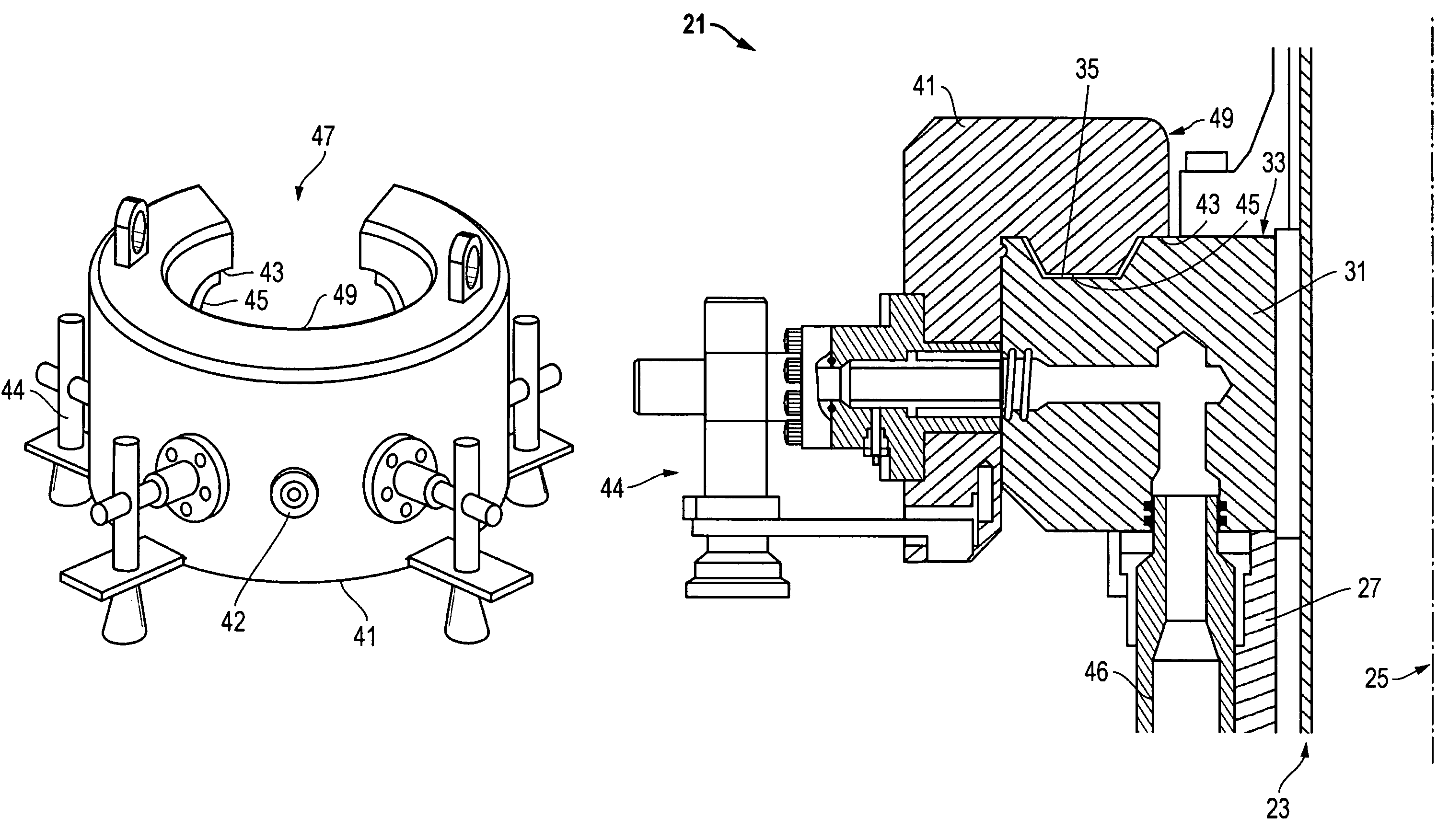
[0016]Referring to FIGS. 2-5, one embodiment of a system, method, and apparatus constructed in accordance with the present invention is shown. The present invention comprises a line termination system 21 (FIGS. 3 and 4) for a riser string and is well suited for use with a slip joint 23 having an axis 25 and an outer barrel27 with an outer diameter 29. A ring adapter 31 is mounted to the outer barrel 27 of the slip joint 23. The ring adapter 31 has an upper surface 33 with a recess 35 formed therein and, in one embodiment, the ring adapter 31 is circumferentially continuous with respect to the slip joint 23.

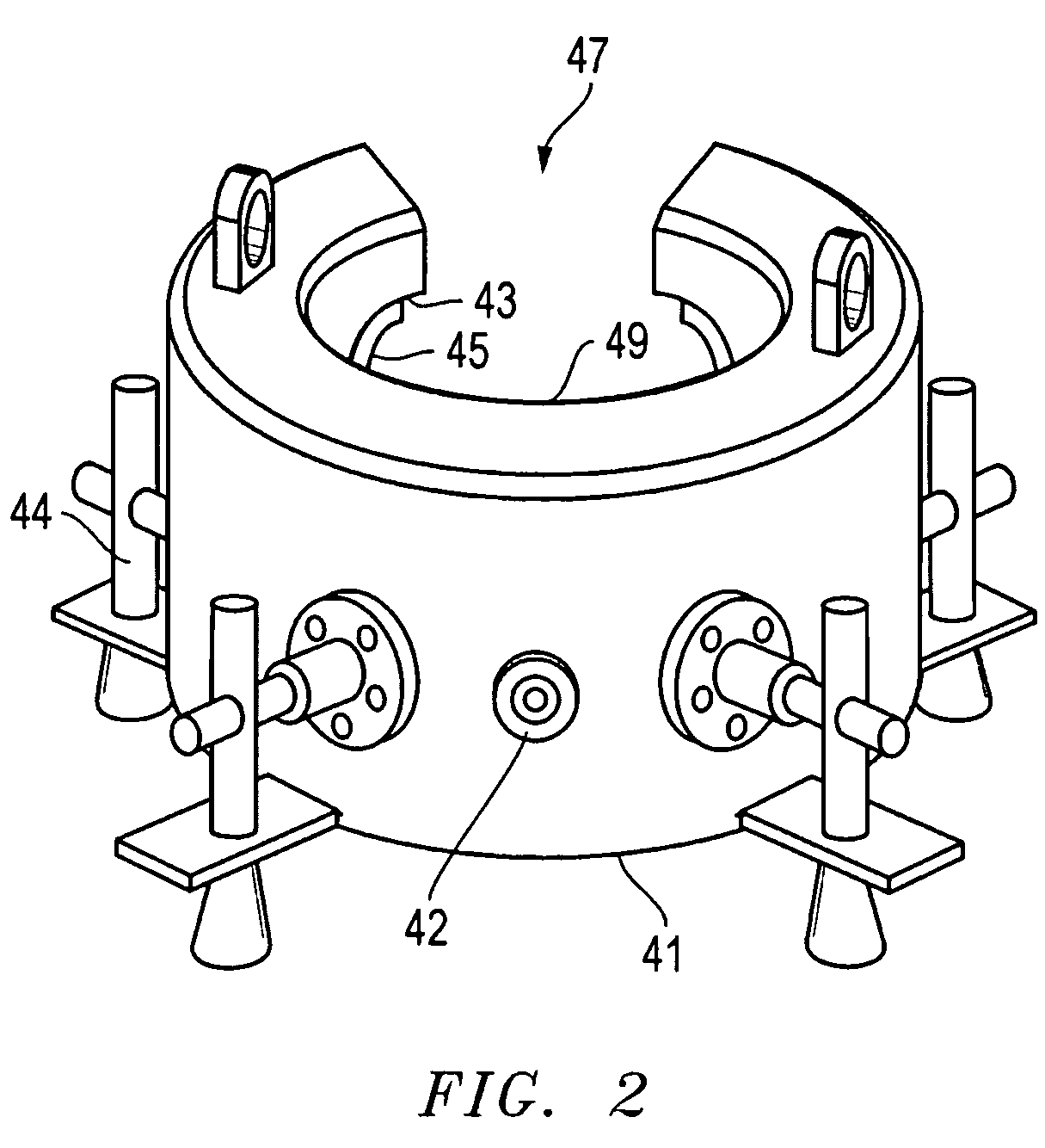
[0017]The line termination system 21 also includes a ring body 41 (FIGS. 2-4) that is mounted to the ring adapter 31. The ring body 41 has a lower surface 43 (FIG. 4) with a protuberance 45 extending therefrom. The protuberance 45 seats in the recess 33 on the ring adapter 31 to provide radial alignment between the ring adapter 31 and ring body 41. In one embodiment, the protubera...


PUM


Abstract

A line termination assembly for a riser string has a ring adapter mounted to a slip joint and a ring body mounted on top of the ring adapter. The ring adapter radially aligns with the ring body, which forms an inner diameter for receiving the slip joint. The ring body also has a discontinuity for radial access to the inner diameter, such that the ring body is circumferentially discontinuous. The discontinuity defines a chord dimension that exceeds the outer diameter of the slip joint, such that the slip joint may move radially through the discontinuity and into the inner diameter during assembly and disassembly of the system. Fluid bearings and tension rings are mounted to the slip joint and are axially spaced apart from the ring adapter and the ring body.

Description

BACKGROUND OF THE INVENTION[0001]1. Technical Field[0002]The present invention relates in general to terminating choke, kill, and auxiliary lines for riser strings on an offshore drilling rig and, in particular, to an improved system, method, and apparatus for a line termination system that is radially-movable relative to the riser string.[0003]2. Description of the Related Art[0004]Offshore drilling rigs must compensate for many environmental hazards including tidal conditions, ocean swells, and weather conditions such as wind and severe weather. The forces generated by these hazards cause significant motion of the rig that must be compensated to maintain the continuity of the riser string that extends down from the rig and is fixed to the ocean floor. A slip joint is typically used near an upper end of the riser string to compensate for vertical motion of the rig. The slip joint compensates for motion with inner and outer barrels that move axially relative to each other. The vario...

Claims


Application Information

Patent Timeline
Patent Type & Authority Patents(United States)
IPC IPC(8): E21B29/12
CPCE21B17/01E21B19/006E21B17/085
Inventor REAMS, JAMES R.
Owner VETCO GRAY
Learn More