Automatic transmission system and method for controlling automatic transmission apparatus

a transmission system and automatic transmission technology, applied in the direction of gearing control, gearing element, belt/chain/gearing, etc., can solve the problems of inability to correctly recognize the actual shift range, power interruption or failure of the sbw controller, etc., and achieve the effect of more reliable operation

Active Publication Date: 2009-08-11
DENSO CORP +1
View PDF10 Cites 19 Cited by
  • Summary
  • Abstract
  • Description
  • Claims
  • Application Information

AI Technical Summary

Problems solved by technology

Thus, an instantaneous power interruption or failure (an instantaneous stop of the power supply) of the SBW controller may possibly occur due to some unexpected reason (e.g., unexpected electrical contact malfunctioning).
However, in the case of the electric shift range change apparatus, there is no mechanical connection between the shift range setting device and the shift range change mechanism, as described above.
Thus, when the power supply of the SBW controller is instantaneously interrupted, and thereby the SBW controller is restarted, it may possibly happen that the SBW controller cannot correctly recognize the actual shift range.

Method used


Image

  • Automatic transmission system and method for controlling automatic transmission apparatus
  • Automatic transmission system and method for controlling automatic transmission apparatus
  • Automatic transmission system and method for controlling automatic transmission apparatus

Examples


first embodiment

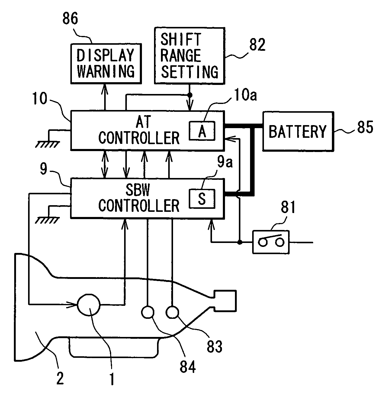
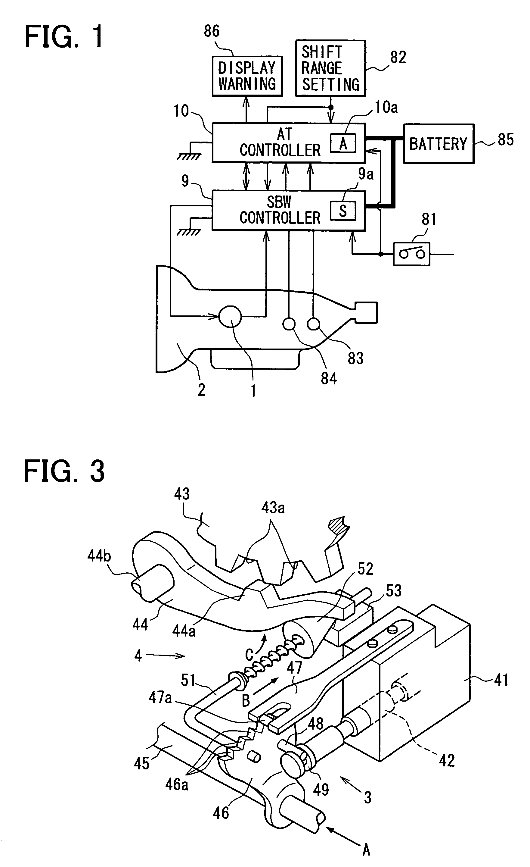
[0037]In the following description, a main structural feature of a first embodiment of the present invention will be first described with reference to FIGS. 1 to 3, and then a characteristic operation of the first embodiment will be described with reference to FIGS. 4 to 11.

[0038]A shift range change apparatus is an apparatus that changes an operational position of a shift range change mechanism 3 (including a parking change mechanism 4 shown in FIG. 3), which is installed in a vehicle automatic transmission apparatus 2 (FIG. 1), through operation of an electric actuator 1.

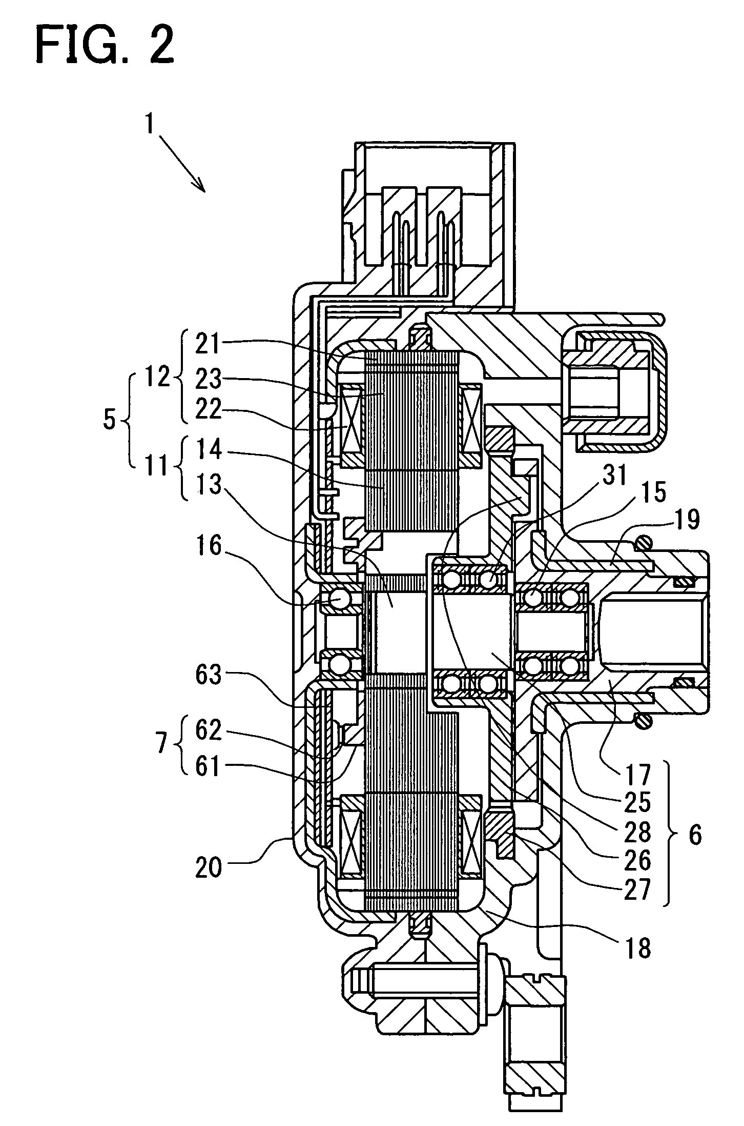
[0039]The electric actuator 1 is a servo mechanism, which drives the shift range change mechanism 3. Specifically, the electric actuator 1 includes a synchronous electric motor 5, a speed reducer 6 and an encoder 7. The speed reducer 6 reduces a rotational speed of the electric motor 5 and drives the shift range change mechanism 3. The encoder 7 senses a rotational angle of the electric motor 5 and an output shaft...

second embodiment

[0162]A second embodiment of the present invention will be described with reference to FIGS. 12 and 13. In the following description, the components similar to those of the first embodiment will be indicated by the same numerals.

[0163]In the first embodiment, the example of the process of step E7 executed by the AT controller 10 at the time of instantaneous power interruption of the SBW controller 9 includes the use of the seventh restarting means to place the automatic transmission apparatus 2 into the neutral state and to determine the output shaft position S by the execution of the wall position sensing process through the SBW controller 9.

[0164]In the second embodiment, the AT controller 10 include the eighth restarting means, which is used in the process of step E7 executed by the AT controller 10 at the time of instantaneous power interruption of the SBW controller 9. The eighth restarting means performs the following first to third steps. In the first step, the rotational dir...


PUM


Abstract

An SBW storage of an SBW controller stores a rotational angular position of an output shaft of an electric actuator. When the SBW controller is restarted due to instantaneous power interruption, the SBW controller maintains and uses the current angular position of the output shaft, which is stored in the SBW storage device, as a latest rotational angular position of the output shaft that is used to drive a shift range change mechanism upon satisfaction of the following conditions: the electric motor has not been driven before the instantaneous power interruption, and the current rotational angular position of the output shaft, which is stored in the SBW storage device, is not destroyed.

Description

CROSS REFERENCE TO RELATED APPLICATION[0001]This application is based on and incorporates herein by reference Japanese Patent Application No. 2005-165975 filed on Jun. 6, 2005.BACKGROUND OF THE INVENTION[0002]1. Field of the Invention[0003]The present invention relates to an automatic transmission system having an automatic transmission apparatus and a method for controlling the automatic transmission apparatus.[0004]2. Description of Related Art[0005]An electric shift range change apparatus, which changes a shift range change mechanism of an automatic transmission apparatus through use of an electric actuator, has been proposed (see, for example, Japanese Unexamined Patent Publication No. H03-186657 and Japanese Unexamined Patent Publication No. 2004-56858 corresponding to US2003 / 0222617A1 and US2006 / 0033464A1).[0006]In this electric shift range change apparatus, there is no mechanical connection between a shift range setting device, i.e., a shift range setting means (e.g., a mecha...

Claims


Application Information

Patent Timeline
Patent Type & Authority Patents(United States)
IPC IPC(8): B60W50/02F16H61/12F16H61/28
CPCF16H61/12F16H61/32F16H2061/283F16H2061/326Y10S477/907Y10T74/19251
Inventor KASHIWAGI, TOMOYUKIMATSUZAKI, HARUKIHORI, MASASHI
Owner DENSO CORP
Why Eureka
Try Eureka