Method and system for cleaning heat exchanger tube bundles

a technology of heat exchanger tubes and bundles, which is applied in the direction of flushing cleaning, lighting and heating apparatus, and cleaning using liquids. it can solve the problems of cleaning fluid escape, some of the fumes of prior art systems, and possible cleaning fluid escap

Inactive Publication Date: 2009-08-18
NAT HEAT EXCHANGE CLEANING CORP
View PDF10 Cites 6 Cited by
  • Summary
  • Abstract
  • Description
  • Claims
  • Application Information

AI Technical Summary

Problems solved by technology

While the prior art mobile cleaner provided an adequate cleaning of the heat exchanger tubes, it had several problems associated with its use.
The first problem was that the prior art system vented some of the fumes from the cleaning solution directly into the atmosphere.
Another problem involved the two top doors that did not completely seal against the top of the container or with each other, allowing escape of fumes and possibly cleaning fluid.
These and other problems associated with the prior art identify a need for a new method and system for cleaning heat exchanger tube bundles.

Method used


Image

  • Method and system for cleaning heat exchanger tube bundles
  • Method and system for cleaning heat exchanger tube bundles
  • Method and system for cleaning heat exchanger tube bundles

Examples


Embodiment Construction

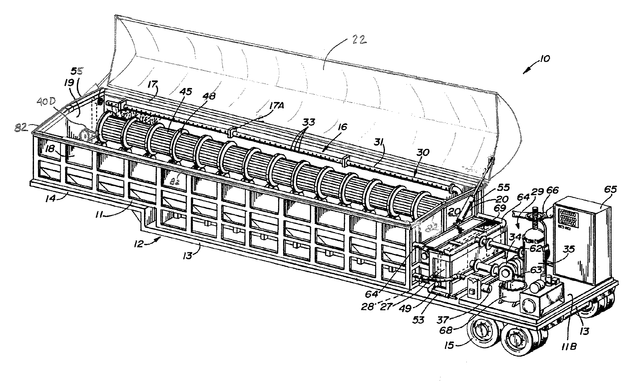
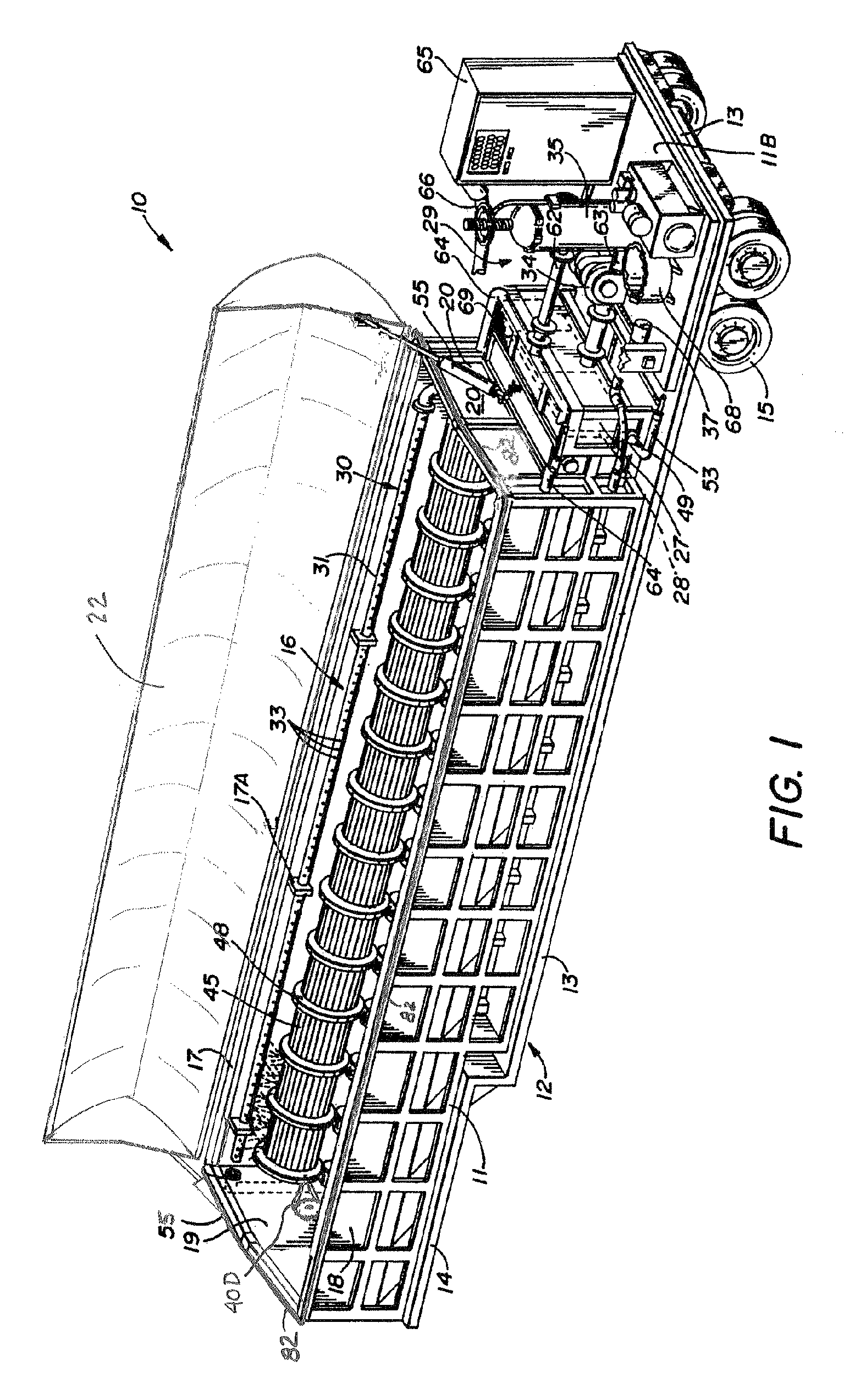
[0017]Referring to FIGS. 1-4 of the drawings, a mobile self-contained heat exchanger tube bundle cleaning device 10 can be seen having a mobile base 11 mounted on a trailer configuration 12 having a bed 13 and a trailer hitch portion 14 with associated wheel assemblies 15 thereon. While shown as a trailer configuration, the unit 10 is also contemplated as an integral frame unit that is transported to a location on a flatbed or the like and dismounted at the facility where the cleaning is to take place.

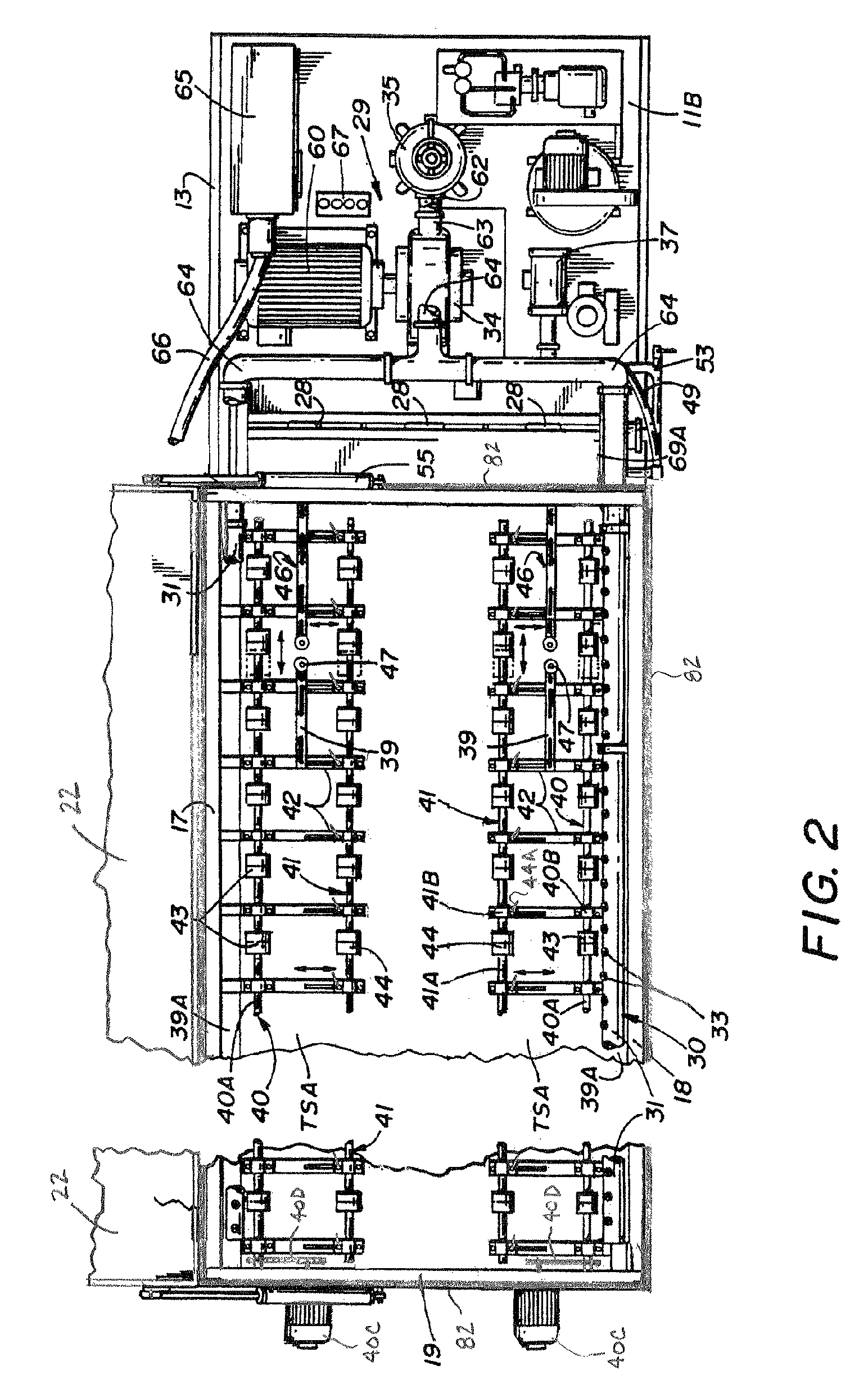
[0018]The mobile base 11 includes a main tube bundle receiving reservoir enclosure 16 having spaced, oppositely disposed sidewalls 17 and 18 integral respective end walls 19 and 20 and an interconnected bottom structure 21. The main tube bundle receiving reservoir enclosure 16 has a domed top door 22 that is pivotally secured to the upper edges of sidewall 17. The door 22 pivots inwardly towards sidewall 18 forming an enclosed sealed cleaning area within the tube bundle receiving reser...


PUM


Abstract

A method and system utilizing a mobile cleaning unit for providing cleaning of heat exchanger tube bundles. The mobile cleaning unit utilizes a pressurized seal positioned about top door of the cleaning enclosure to provide a fluid and vapor lock of the cleaning enclosure. An oxygen purging system of the cleaning enclosure, the cleaning fluid reservoir, and the control panels provides additional safety. The mobile cleaning unit can use cleaning fluid produced at the facility site and return the cleaning fluid to the facility site for reprocessing after the heat exchanger tube bundles are cleaned.

Description

[0001]This application is a continuation of PCT International Application Number PCT / IB2005 / 051909 filed Jun. 9, 2005, which claims the benefit of U.S. Provisional Patent Application Ser. No. 60 / 656,430, filed Feb. 24, 2005, both applications hereby incorporated by reference.TECHNICAL FIELD[0002]The present invention relates to a method and system for cleaning heat exchanger tube bundles and, more particularly, to a method and system for providing a safe, economical, and environmentally friendly cleaning of heat exchanger tube bundles using cleaning fluid produced on site and reprocessed on site, such that long distance transport of cleaning solution is not required.BACKGROUND OF THE INVENTION[0003]A mobile cleaner for heat exchanger tube bundles is disclosed in commonly owned U.S. Pat. No. 5,437,296. While the prior art mobile cleaner provided an adequate cleaning of the heat exchanger tubes, it had several problems associated with its use. The first problem was that the prior art ...

Claims


Application Information

Patent Timeline
Patent Type & Authority Patents(United States)
IPC IPC(8): B08B3/02
CPCB08B3/02B08B9/023F28G9/00F28G3/166F28D7/16F28G2015/006
Inventor JOSEPH, CARROLL E.
Owner NAT HEAT EXCHANGE CLEANING CORP
Why Eureka
Try Eureka