Production casing ripper

a production casing and ripper technology, applied in the field of production casing rippers, can solve the problem that none of these inventions cuts a continuous vertical slot in the production casing

Inactive Publication Date: 2009-09-01
LIQUID GOLD WELL SERVICE
View PDF27 Cites 8 Cited by
  • Summary
  • Abstract
  • Description
  • Claims
  • Application Information

AI Technical Summary

Benefits of technology

[0018]In a preferred embodiment, the swedge comprises a weep hole, wherein the plunger comprises one or more O rings, wherein when the weep hole is plugged and hydraulic fluid is introduced through the swedge, the hydraulic fluid is fully contained within the swedge, the spring housing, and the main housing above the plunger, and wherein when the weep hole is not plugged and hydraulic fluid is introduced through the swedge, the weep hole allows fluid pressure inside and outside of the ripper to be equalized.

Problems solved by technology

The prior art includes numerous examples of production casing perforators or cutters, but none of these inventions cuts a continuous vertical slot in the production casing through the use of a single, hydraulically-operated plunger.
The tools described in these patents are designed to punch a single hole in the production casing; they are not designed to cut a continuous vertical slot for any significant distance.

Method used


Image

  • Production casing ripper
  • Production casing ripper
  • Production casing ripper

Examples


Embodiment Construction

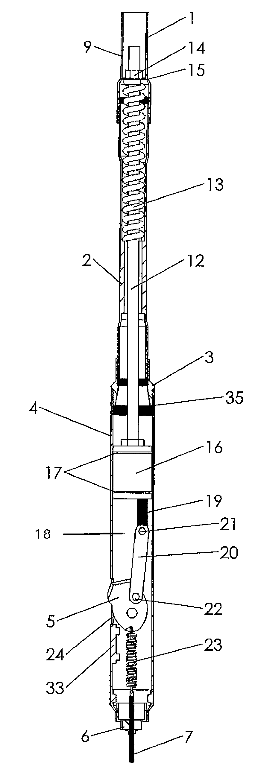
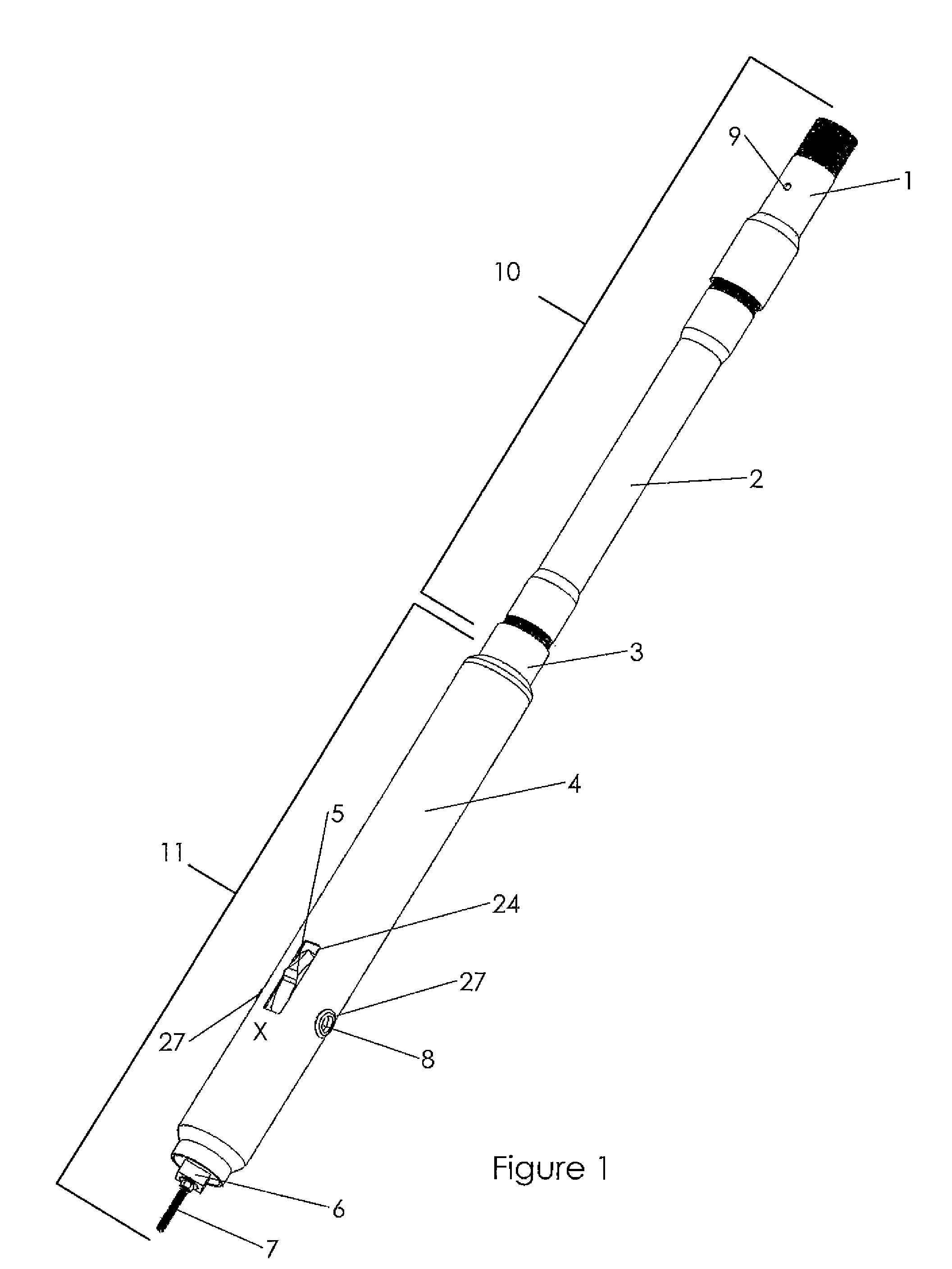
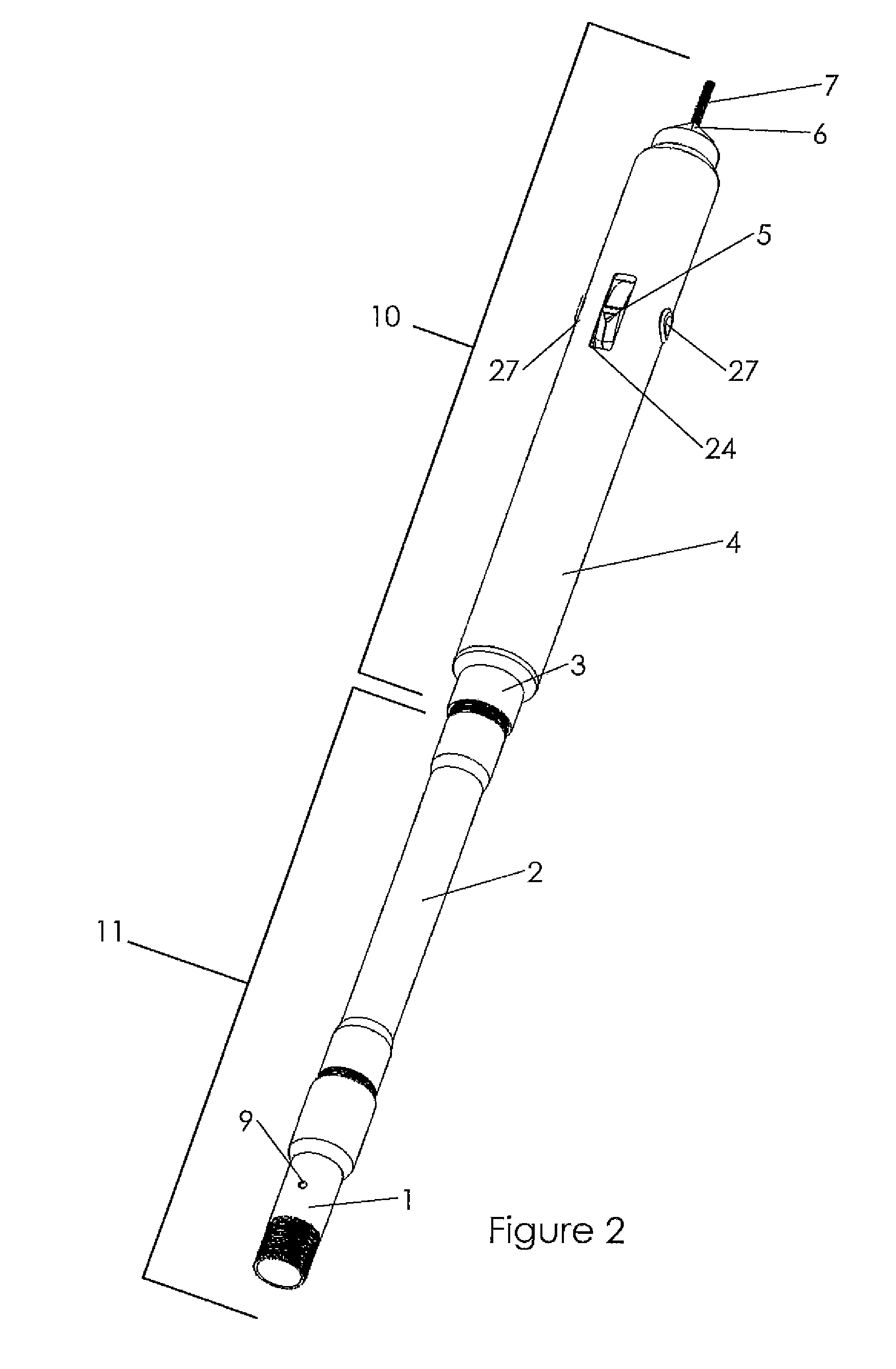
[0072]The present invention is a production casing ripper that is designed to cut a continuous vertical slot in the casing of oil, gas or water wells. As explained further below, the blade on the tool is engaged through the use of hydraulics and a plunger. A safety mechanism on the tool ensures that the blade disengages after the fluid pressure is released.

[0073]The present invention is intended to be used for plug and abandonment of older oil and gas wells where it is necessary to replace the concrete behind the production casing. It can also be used during production to evaluate the fluid in a zone behind the production casing (where the casing has not already been perforated) by ripping a slot in the casing at the zone to be evaluated. In water wells, the present invention can be used to perforate holes in the production tubing where the original holes have become plugged due to calcium deposits. These are but a few of the numerous possible applications of the present invention, ...


PUM

PropertyMeasurementUnit
pressuresaaaaaaaaaa
diameteraaaaaaaaaa
hydraulic pressureaaaaaaaaaa

Abstract

A production casing ripper comprising a swedge; spring housing; coupling; main housing; end piece; blade; and means for connecting the blade to the plunger; wherein the blade is situated inside of the main housing; wherein a plunger is situated inside of the main housing; wherein a primary spring is situated inside of the spring housing; wherein a primary pull rod is connected to the primary spring at one end and to the plunger at the other end; wherein when hydraulic pressure is introduced through the swedge, the plunger moves downward inside of the main housing and causes the blade to extend through an aperture in the main housing; and wherein when the hydraulic pressure is released, the primary spring causes the plunger to return to its original position, thereby causing the blade to retract.

Description

BACKGROUND OF THE INVENTION[0001]1. Field of the Invention[0002]The present invention relates generally to the field of oil, gas and water wells and, more specifically, to a production casing tipper that cut a continuous vertical slot in well production casing.[0003]2. Description of the Related Art[0004]The prior art includes numerous examples of production casing perforators or cutters, but none of these inventions cuts a continuous vertical slot in the production casing through the use of a single, hydraulically-operated plunger. The prior art generally falls into three categories: casing cutters, single-hole punchers, and under reamers. The first category is represented by U.S. Pat. No. 1,777,713 (Braden, 1928); U.S. Pat. No. 2,049,450 (Johnson, 1936); U.S. Pat. No. 2,284,211 (Justice, 1942); U.S. Pat. No. 2,322,695 (Kinzbach, 1943); U.S. Pat. No. 2,525,007 (Worden et al., 1950); U.S. Pat. No. 2,725,936 (Hester, 1955); U.S. Pat. No. 2,859,943 (Chadderdon, 1958); U.S. Pat. No. 3,...

Claims


Application Information

Patent Timeline
Patent Type & Authority Patents(United States)
IPC IPC(8): E21B29/00E21B43/11
CPCB23D11/00E21B43/112E21B29/00B23D21/14Y10T83/398
Inventor SCHWINDT, SHANE
Owner LIQUID GOLD WELL SERVICE
Why Eureka
Try Eureka