Method and device to control a computer system utilizing a fluid flow

a computer system and fluid flow technology, applied in the direction of machines/engines, electrophonic musical instruments, instruments, etc., to achieve the effect of facilitating user control of a computer system and facilitating control of the computer system

Inactive Publication Date: 2009-09-01
INPUTIVE CORP
View PDF18 Cites 6 Cited by
  • Summary
  • Abstract
  • Description
  • Claims
  • Application Information

AI Technical Summary

Benefits of technology

[0016]According to one aspect of the present invention, there is provided a device to facilitate a user control of a computer system. The device includes a movable portion movable by a fluid flow of a generated by a user of the device, and a converter to convert movement of the movable portion into an electrical signal to facilitate control of the computer system.

Problems solved by technology

However, it may appear necessary to be able to control a computer or electronic system without resorting to using the hands, especially when the user is unable to do so.

Method used


Image

  • Method and device to control a computer system utilizing a fluid flow
  • Method and device to control a computer system utilizing a fluid flow
  • Method and device to control a computer system utilizing a fluid flow

Examples


Embodiment Construction

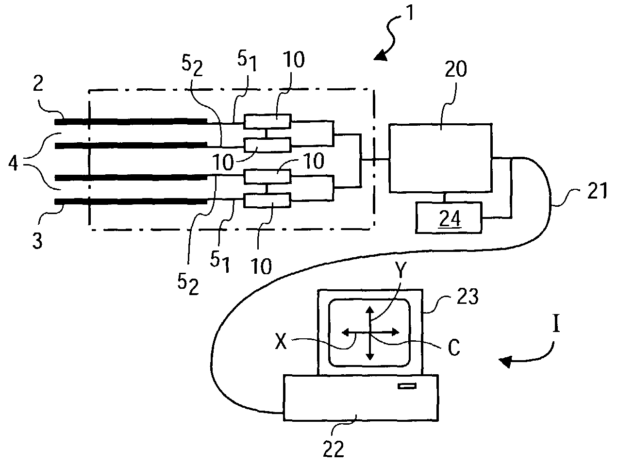
[0023]FIG. 1 diagrammatically illustrates an application example of the invention for a device denoted in its entirety by the reference 1 controlled by the breath of a user for moving the cursor C of a computer system 1.

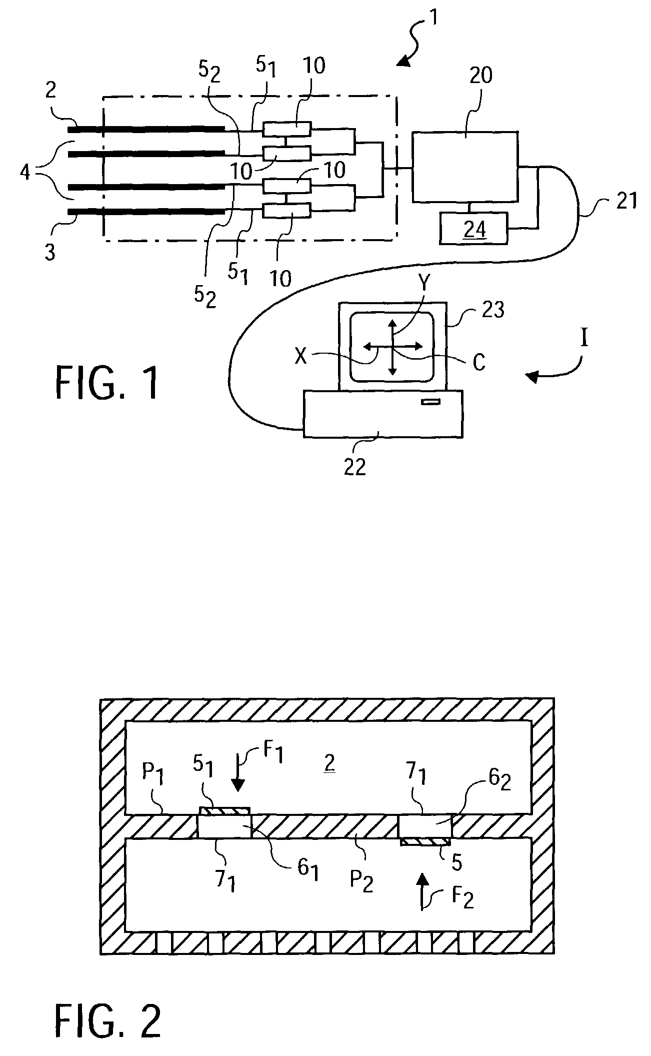
[0024]The monitoring device 1 comprises two tubes 2, 3 associated with a movement direction X or Y of the cursor. Each tube 2, 3 has an orifice 4 at the level of which an individual can breathe in or suck up air. Opposite the orifices 4, each tube 2, 3 has two free segments, one 51 of the latter being stressed by the air expired or on expiration, whereas the other 52 is stressed by the inspired air or on inspiration.

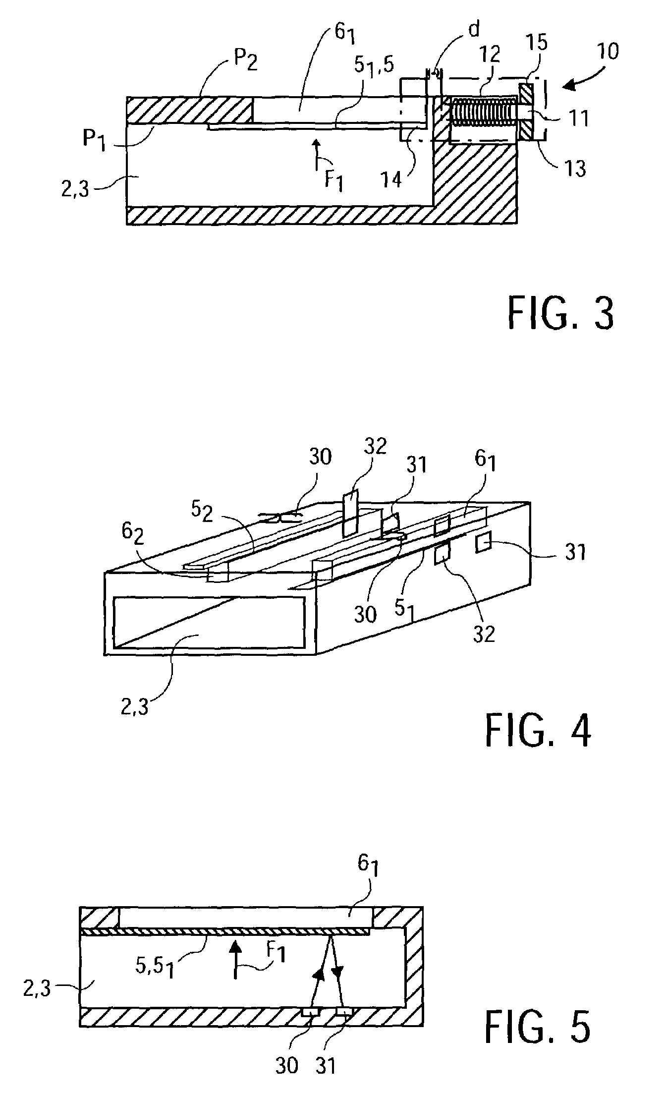
[0025]As shown on FIG. 1, each segment 51 and 52 is mounted opposite a channel 61 and 62 fitted in the wall of the tube 2 or 3. Each channel 61, 62 has dimensions similar to the dimension of the associated segment whilst being slightly larger so that the segment can flap in the channel. So as to ensure vibrating of each of the segments 51, 52 by its corre...


PUM


Abstract

A device, to facilitate a user control of a computer system, includes a movable portion movable by a fluid flow of a generated by a user of the device, and a converter to convert movement of the movable portion into an electrical signal to facilitate control of the computer system.

Description

[0001]The present application is a continuation of application Ser. No. 09 / 913,398 filed Aug. 10, 2001 now U.S. Pat. No. 6,574,571.FIELD OF THE INVENTION[0002]The invention concerns the technical field for of controlling an electronic or computer systems.BACKGROUND OF THE INVENTION[0003]A device known as a mouse is used for transforming movements into controls required by a user. The mouse is formed by a box equipped with electronic means connected to the computer for transforming the movements of the box on the working surface into a movement of the cursor or pointer on the computer screen.[0004]Thus, a mouse more generally includes a ball for rolling over the working surface, sensors to detect the movements of the ball and means for processing the electric signals of the sensors. The processing means are connected to the computer by an electric cable or a Hertzien or infrared link. The processing means have been designed to deliver signals recognised by the protocol of the port to...

Claims


Application Information

Patent Timeline
Patent Type & Authority Patents(United States)
IPC IPC(8): G01F1/00G06F3/043G06F3/033G10H3/16
CPCG10H3/16
Inventor BONNAT, PIERRE
Owner INPUTIVE CORP
Why Eureka
Try Eureka