Hole saw electrical box for direct mounting of electrical fixtures or devices to a wall

a technology of electrical fixtures or devices and electrical boxes, which is applied in the direction of coupling device connections, lighting support devices, lighting and heating apparatus, etc., can solve the problem of difficult to determine whether the clamps are rotated to the proper position for tightening the box to the sheetrock

Active Publication Date: 2009-09-08
ARLINGTON INDS
View PDF14 Cites 29 Cited by
  • Summary
  • Abstract
  • Description
  • Claims
  • Application Information

AI Technical Summary

Problems solved by technology

One problem with this method is that the homeowner must make a hole large enough to accommodate the flip out clamps that extend outward from the sidewalls of the electrical box.
Additionally, once the electrical box is pushed through the sheetrock, the clamps are out of view and it is difficult to determine whether the clamps are rotated to the proper position for tightening the box to the sheetrock.

Method used


Image

  • Hole saw electrical box for direct mounting of electrical fixtures or devices to a wall
  • Hole saw electrical box for direct mounting of electrical fixtures or devices to a wall
  • Hole saw electrical box for direct mounting of electrical fixtures or devices to a wall

Examples


Embodiment Construction

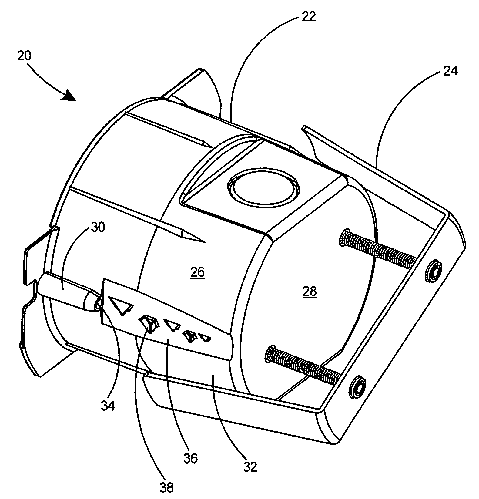
[0073]With reference to FIG. 1 there is shown a preferred embodiment of the present invention, an electrical box assembly 20. The electrical box assembly 20 includes an electrical box 22 and a bracket 24 that is adjustable with respect to the electrical box 22. The electrical box 22 includes a sidewall 26, a back wall 28, and one or more bosses 30 extending from the outer surface 32 of the sidewall 26. The bosses 30 extend partially toward the back wall 28 of the electrical box 22 and terminate in a back end 34. The sidewall 26 includes a flat portion 36 extending from the back end 34 of each boss 30 to the back wall 28. A plurality of teeth 38 are provided in the flat portion 36 of the sidewall 26 extending between each boss 30 and the back wall 28.

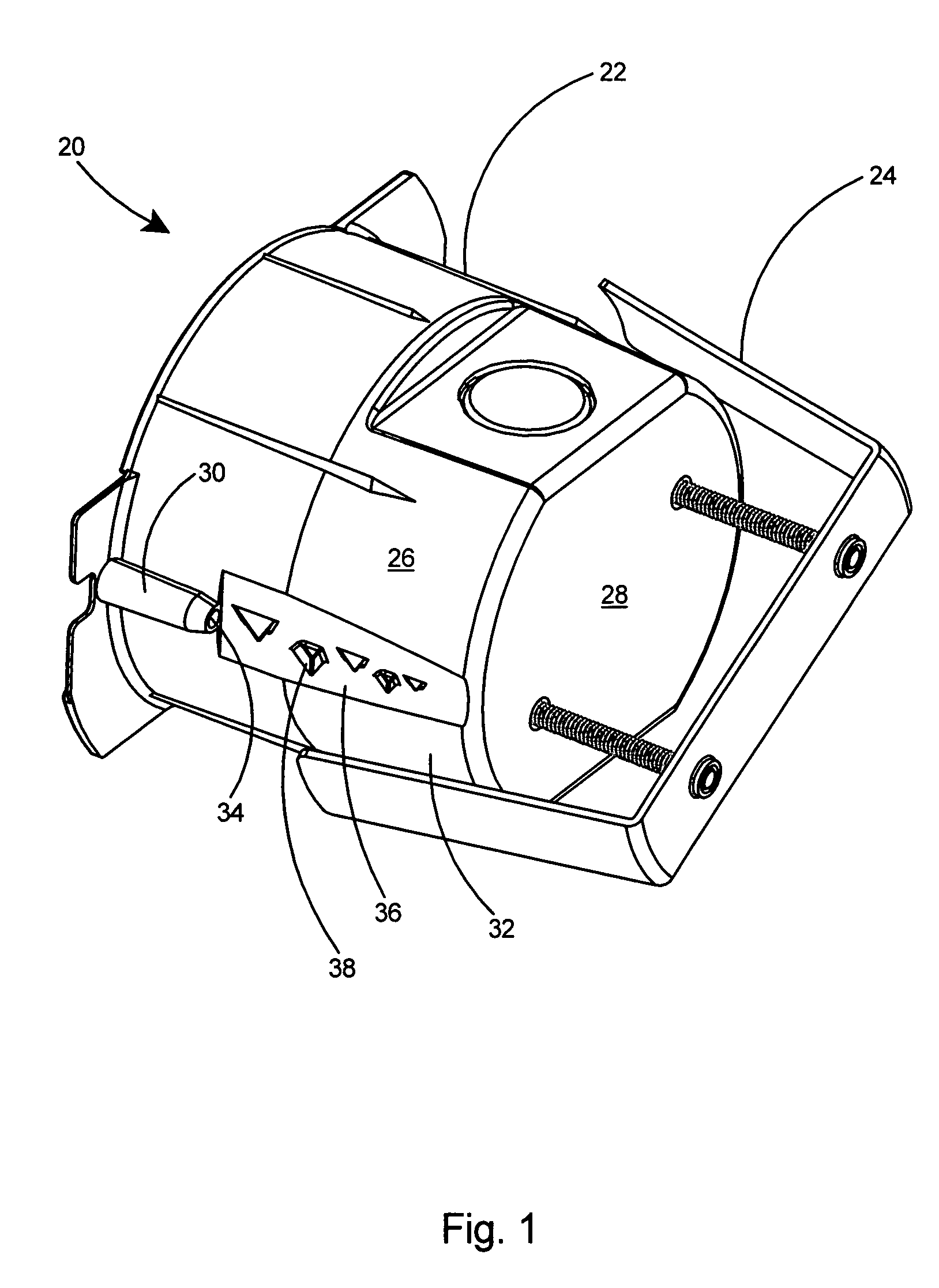
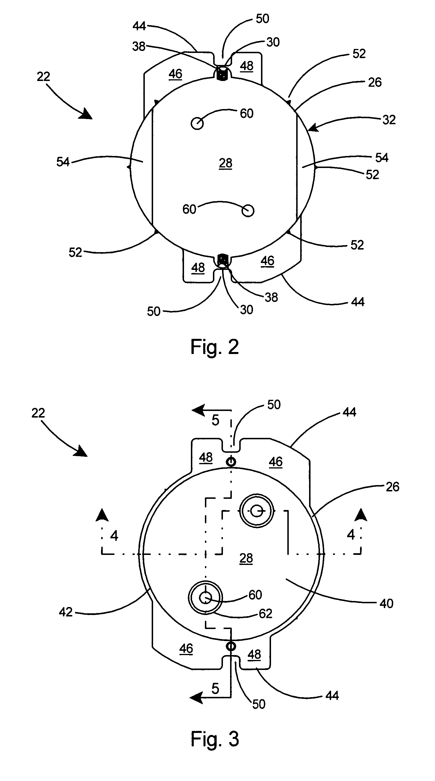
[0074]Referring to FIGS. 2 and 3, the back wall 28 and sidewall 26 of the electrical box 22 define a cavity 40 (see FIG. 3) therein for accepting electrical cables and wiring connections (not shown) therein. The electrical box 22 include...


PUM


Abstract

An electrical box assembly for mounting an electrical device or fixture on a wall. The electrical box assembly includes a box having a back wall and a sidewall defining an enclosure, and flanges and bosses extending outward from the sidewall. Teeth are provided along the outer sidewall of the box in alignment with and extending from each boss to the back wall. An elongated bracket with resilient legs is adjustably connected to the back wall of the box. After a hole is made in the drywall, the teeth rip a path for the bosses as the electrical box assembly is pushed into the hole. An adjustment arrangement including fasteners is provided for adjusting the distance of the bracket with respect to the box and securing the box to the wall. The clamping action of the bracket legs and flange on the drywall hold the electrical box assembly secure to the wall.

Description

FIELD OF THE INVENTION[0001]This invention relates to electrical boxes for mounting an electrical device or light fixture to a wall and specifically to an electrical box for mounting an electrical device or light fixture to a wall in a retrofit application.BACKGROUND OF THE INVENTION[0002]To improve the lighting or electrical access in their homes, homeowners frequently retrofit their homes with additional electrical devices or light fixtures. Typically this is done by locating an appropriate stud, removing the sheetrock, and installing a standard electrical box that is secured to the studs with fasteners. This method typically involves replacing or repairing a substantial amount of sheetrock around the newly installed electrical box.[0003]An alternative method includes a junction box with flip out clamps. In this method, a hole is made in the sheetrock and the electrical box including the flip out clamps is pushed through the hole. The clamps, which are then located behind the shee...

Claims


Application Information

Patent Timeline
Patent Type & Authority Patents(United States)
IPC IPC(8): H01H9/02
CPCH02G3/123F21V21/04Y10S248/906
Inventor GRETZ, THOMAS J.
Owner ARLINGTON INDS
Why Eureka
Try Eureka