
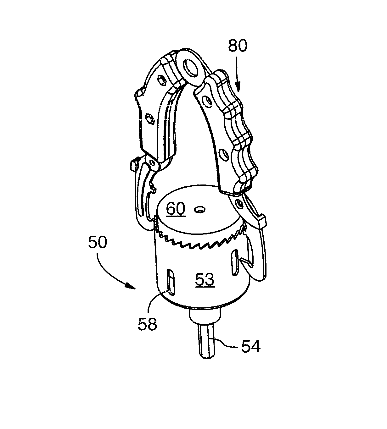
Hole saw system with improved slug removability

a technology of slug removal and hole saw, which is applied in the field of hole saws, can solve the problems of slug removal, excessively heavy hole saw and/or particulate ejection, and difficulty in removal of slugs, so as to reduce the overall weight of the hole saw, and facilitate the removal of slugs. or swarfs.

Inactive Publication Date: 2011-11-08
TEAM FAIR HLDG
View PDF36 Cites 35 Cited by
  • Summary
  • Abstract
  • Description
  • Claims
  • Application Information

AI Technical Summary

Benefits of technology

"The present invention provides an improved hole saw system that makes it easier to remove slugs, which are metal pieces that are formed during drilling. The hole saw system includes a slot pair that allows for access to the slug over a longer distance, making it easier to remove. Additionally, the hole saw system is designed to be lighter and easier to remove swarf, which is a byproduct of drilling. Overall, the invention improves the efficiency and ease of use of hole saw systems."

Problems solved by technology

In prior art hole saw systems, there are several inherent issues with respect to slug ejection, excessively heavy hole saws and / or particulate ejection.
Many of these prior art hole saw systems suffer from more than one of these problems.
For instance, with respect to slug ejection, after a hole has been cut by a hole saw, the slug remains in the saw and often is difficult to remove.
Furthermore, current hole saws tend to be quite heavy, particularly those of bi-metal because of the construction method (i.e. thick steel plate backing).
The weight of a hole saw typically increases power usage requirements which is not ideal especially for battery-operated drills, since the battery runs low too quickly.
Therefore, heavier prior art hole saws are more costly to use as batteries are drained in a faster time frame.
Even if a user was using rechargeable batteries, there is a consistent need to change batteries in the midst of jobs and / or projects which is time consuming and affects overall work productivity and flow.
These particulates collect in the bottom of the hole saw which can result in further work delays as the user must clean the hole saw to remove these particulates prior to further use.
Also, there are some hole saw systems with ejection apparatus integrated to the hole saw assembly to improve slug ejection, however, these mechanisms require extra components and are costly and complex.

Method used


Image

  • Hole saw system with improved slug removability
  • Hole saw system with improved slug removability
  • Hole saw system with improved slug removability

Examples


Embodiment Construction

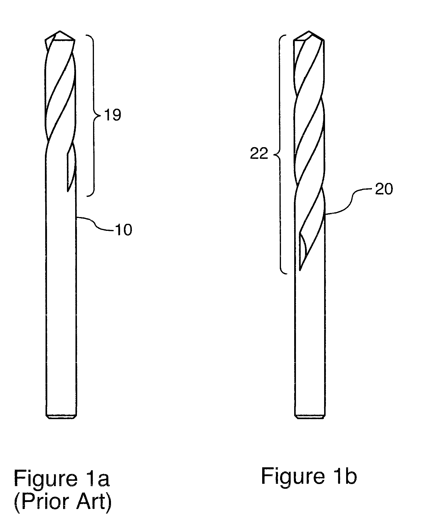
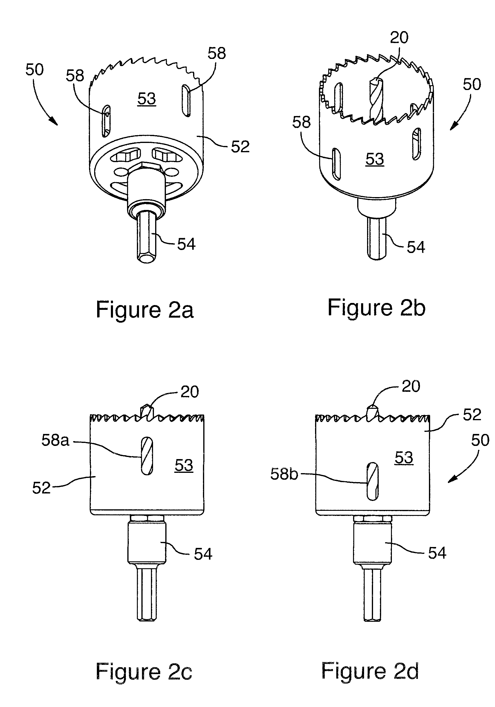
[0038]Generally, the present invention provides a hole saw system which includes an improved hole saw. The hole saw also includes means for improving slug removal, as will be described in more detail below. In one embodiment, the pilot bit being used in the current system has a longer flute section than current standard drill bits to improve both slug and particulate matter removal. In a further embodiment, the hole saw system also includes a slug removal tool for improving slug removability.

[0039]FIGS. 1a and 1b illustrate one feature of the current invention. As shown, FIG. 1a is a prior art pilot bit 10 while FIG. 1b is a pilot bit 20 for use with the hole saw system. The pilot bit 20 includes an extended flute section 22 (extended with respect to the flute section 12 of the prior art pilot bit 10). The extended flute section 22 provides improved material, or particulate, removal as the pilot bit advances and the hole is being cut as the cut material travels more readily into the...


PUM

PropertyMeasurementUnit
weightaaaaaaaaaa
longitudinal distanceaaaaaaaaaa
thickaaaaaaaaaa

Abstract

There is provided a hole saw system comprising a hole saw including a bottom portion and a body portion; a mandrel, including apparatus for receiving the hole saw; wherein the hole saw includes a plurality of slot pairs, the slot pairs being offset from each other on the body portion allowing a tool to be inserted into one of the slot pairs for removal of a slug.

Description

CROSS REFERENCE TO RELATED APPLICATIONS[0001]This application claims the benefit of priority of U.S. Provisional Patent Application No. 60 / 953,221 filed Aug. 1, 2007, which is incorporated herein by reference in its entirety.FIELD OF THE INVENTION[0002]The present invention relates generally to hole saws. More particularly, the present invention relates to a hole saw system with improved slug removability.BACKGROUND OF THE INVENTION[0003]In prior art hole saw systems, there are several inherent issues with respect to slug ejection, excessively heavy hole saws and / or particulate ejection. Many of these prior art hole saw systems suffer from more than one of these problems.[0004]For instance, with respect to slug ejection, after a hole has been cut by a hole saw, the slug remains in the saw and often is difficult to remove. In current solutions, the user must “pop” the slug out by inserting a tool into the hole saw and then pushing, or prying, the slug out.[0005]Furthermore, current h...

Claims


Application Information

Patent Timeline
Patent Type & Authority Patents(United States)
IPC IPC(8): B23B47/34B25B7/00
CPCB23B51/0453B25B7/00B25B9/00B23B2260/078Y10T408/50Y10T408/96Y10T408/895B23B51/0467
Inventor SINGH, SATNAM
Owner TEAM FAIR HLDG
Learn More