Adjustable Depth Hole Saw Assembly

a hole saw and assembly technology, applied in the field of adjustable hole saw assembly, can solve the problems of large cost factor for the user of such prior art hole saw assembly inventory, large cost outlay for the required hole saw, and inability to adjust the depth of the substrate material, etc., and achieve the effect of convenient adjustment in length

Inactive Publication Date: 2011-03-03
COMBINED PRODS
View PDF10 Cites 31 Cited by
  • Summary
  • Abstract
  • Description
  • Claims
  • Application Information

AI Technical Summary

Benefits of technology

[0006]It is one object of the present invention to provide a hole saw assembly wherein the saw cup member is readily adjustable in length to properly cut different thicknesses of the encountered substrate material.
[0008]It is still another object of the present invention to provide at least one extension member which is positioned between the tubular saw cup member and the annular cutting edge member to properly cut various thicknesses of the encountered substrate material.
[0009]It is yet another object of the present invention to provide an adjustable saw cup member which permits the user to lengthen the saw cup member to cut through variable depths of substrate materials.
[0010]It is still a further object of the present invention to provide an adjustable saw cup member which is easy to assemble.
[0013]According to another embodiment of the present invention, the adjustable hole saw assembly may include at least one saw cup extension member positioned between the saw cup member and the annular cutting edge member and secured thereto. This structure permits the hole saw assembly to be readily adjustable in length to properly cut substrate materials having variable thicknesses without the costly expenditure of maintaining an inventory of different length saw cup members to properly engage and to cut the particular thickness of the substrate material encountered as well as to modify the saw cup member to permit cutting of different types of substrate encountered.

Problems solved by technology

Oftentimes the hole saw assembly user encounters a situation where the substrate material is of such a thickness that the depth of the substrate material exceeds the operability of the hole saw assembly.
This inventory of saw cup members represents a significant cost factor for the user of such prior art hole saw assemblies.
Again, this requires a significant cost outlay for the required hole saws, with each hole saw mounting a different annular cutting edge to properly engage the particular different type of substrate material encountered.

Method used


Image

  • Adjustable Depth Hole Saw Assembly
  • Adjustable Depth Hole Saw Assembly
  • Adjustable Depth Hole Saw Assembly

Examples


Embodiment Construction

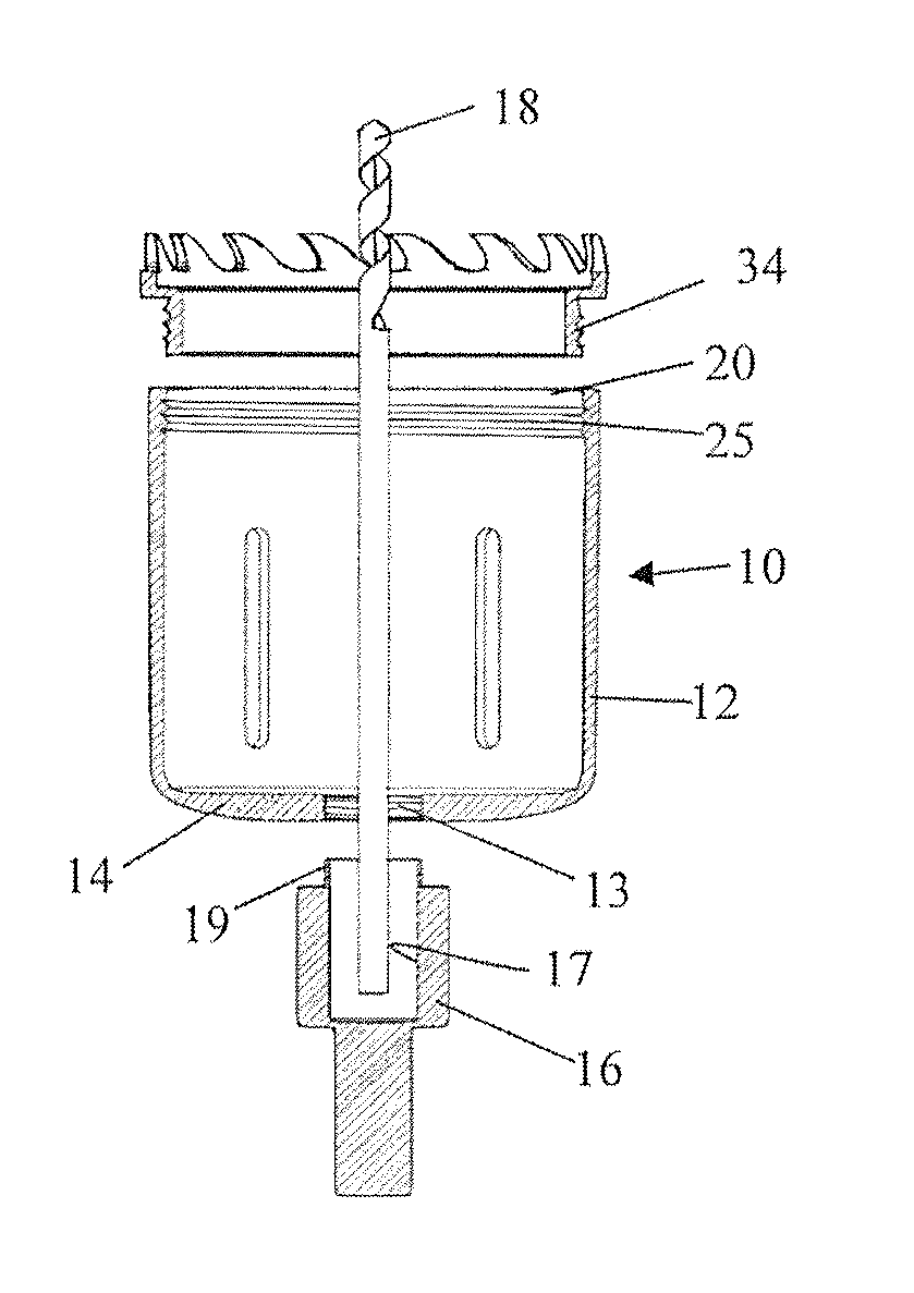
[0027]The detailed description of the present invention refers to the accompanying drawings wherein the same reference numbers have been used throughout the several views to designate the same or similar parts. Referring now to FIG. 1, there is shown a hole saw assembly 10, which includes a tubular saw cup member 12 having a threaded opening 13 in the proximal closed end 14 thereof. The proximal closed end 14 of the saw cup member 12 is structurally arranged to be engaged by a mandrel member 16 having a bore 17 therethrough and a threaded projection 19 thereon which secures the mandrel member to the saw cup member 12. A drill or pilot bit 18 is positioned in the bore of the mandrel member and secured thereto by a set screw 24 to couple the assembly to a drill or other power source (not shown). However, it is within the scope of the present invention that the drill or pilot bit may be secured by other techniques known to those skilled in the art. The pilot bit 18 centrally extends be...


PUM

PropertyMeasurementUnit
diameteraaaaaaaaaa
lengthaaaaaaaaaa
thicknessaaaaaaaaaa

Abstract

A hole saw cup member includes a tubular saw cup member having a closed end arranged to be coupled to a rotary power source and an open end arranged to detachably secure an annular cutting ring member. The invention may include at least one saw cup extension member positioned between the saw cup member and the annular cutting ring member to lengthen the saw cup member to facilitate cutting of substrates having variable thickness.

Description

RELATED APPLICATIONS[0001]This application claims priority to U.S. Provisional Application No. 61 / 237,980 filed on Aug. 28, 2009 the entirety of which is incorporated herein by reference.FIELD OF THE INVENTION[0002]The present invention relates to an adjustable hole saw assembly which permits the user to cut holes in several types of substrate materials with each substrate having various depths of thickness.BACKGROUND OF THE INVENTION[0003]Hole saw assemblies are well known and used in drilling a hole of a desired size in a substrate material. These prior art hole saw assemblies include a tubular hole saw or saw cup member having a threaded opening in the proximal closed end structurally arranged to receive an arbor member which mounts a drill bit or pilot bit to the assembly to couple the assembly to a power source. The prior art tubular saw cup members include an integral cutting edge portion circumferentially extending about the open distal end of the tubular saw cup member.[0004...

Claims


Application Information

Patent Timeline
Patent Type & Authority Applications(United States)
IPC IPC(8): B23B51/04
CPCB23B51/0473B23B51/0406Y10T408/895B23B51/04
Inventor KOZAK, IRA
Owner COMBINED PRODS
Why Eureka
Try Eureka