Belt length adjuster

a technology of belt length and adjuster, which is applied in the direction of buckles, snap fasteners, mechanical devices, etc., can solve the problems of difficult to move the position of the adjuster and adjust the length of the belt, and achieve the effect of convenient belt length adjustment, and easy manufacturing

Active Publication Date: 2011-10-06
SWANS
View PDF35 Cites 13 Cited by
  • Summary
  • Abstract
  • Description
  • Claims
  • Application Information

AI Technical Summary

Benefits of technology

[0017]With the structure as briefly described above, the belt length adjuster of the present invention facilitates adjustment of the length of the belt member, such adjustment of belt length may be done instantly, the manufacturing thereof is easy, and the manufacturing cost is lowered. And furthermore, attachment of one end part of the belt member to the frame is simplified and such attachment can be extremely easy.

Problems solved by technology

The above-described conventional belt length adjuster shown in FIG. 12 has a problem.
Since a lower surface of the other end side of the belt B inserted into the insertion spaces S on both sides of the support frame 12 directly lies on top of and in contact with an upper surface of the one end part of the belt B attached to the support frame 12, and the contact area therebetween is large, which makes frictional resistance very large and makes it difficult to move the position of the adjuster and therefore to adjust the length of the belt.
The foregoing conventional belt length adjuster shown in FIG. 16 has another problem.
Since the exterior member 23 is a separate member from the frame body 21, and needs to be annually wound around the slide-contact frame part 21a, the manufacture thereof is difficult and the manufacturing cost is high.
Further, this belt length adjuster has a further problem.
While the slide body 22 is provided to facilitate shifting the position of the adjuster, since the slide body 22 needs to be slid for shifting the position of the adjuster, such sliding is cumbersome and the adjustment of the belt length cannot be performed instantly.
Moreover, both of the above-described conventional belt length adjusters have a still further problem.

Method used


Image

  • Belt length adjuster
  • Belt length adjuster
  • Belt length adjuster

Examples


Embodiment Construction

[0035]Hereafter, embodiments for carrying out a belt length adjuster of the present invention will be described in detail in conjunction with the drawings.

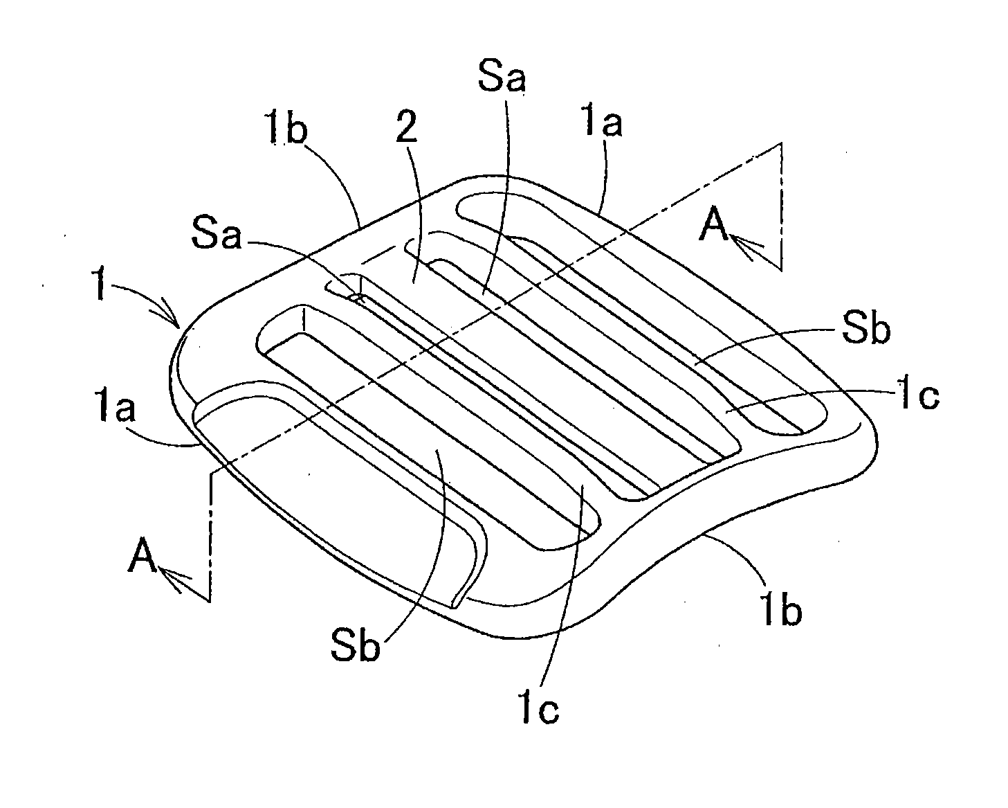
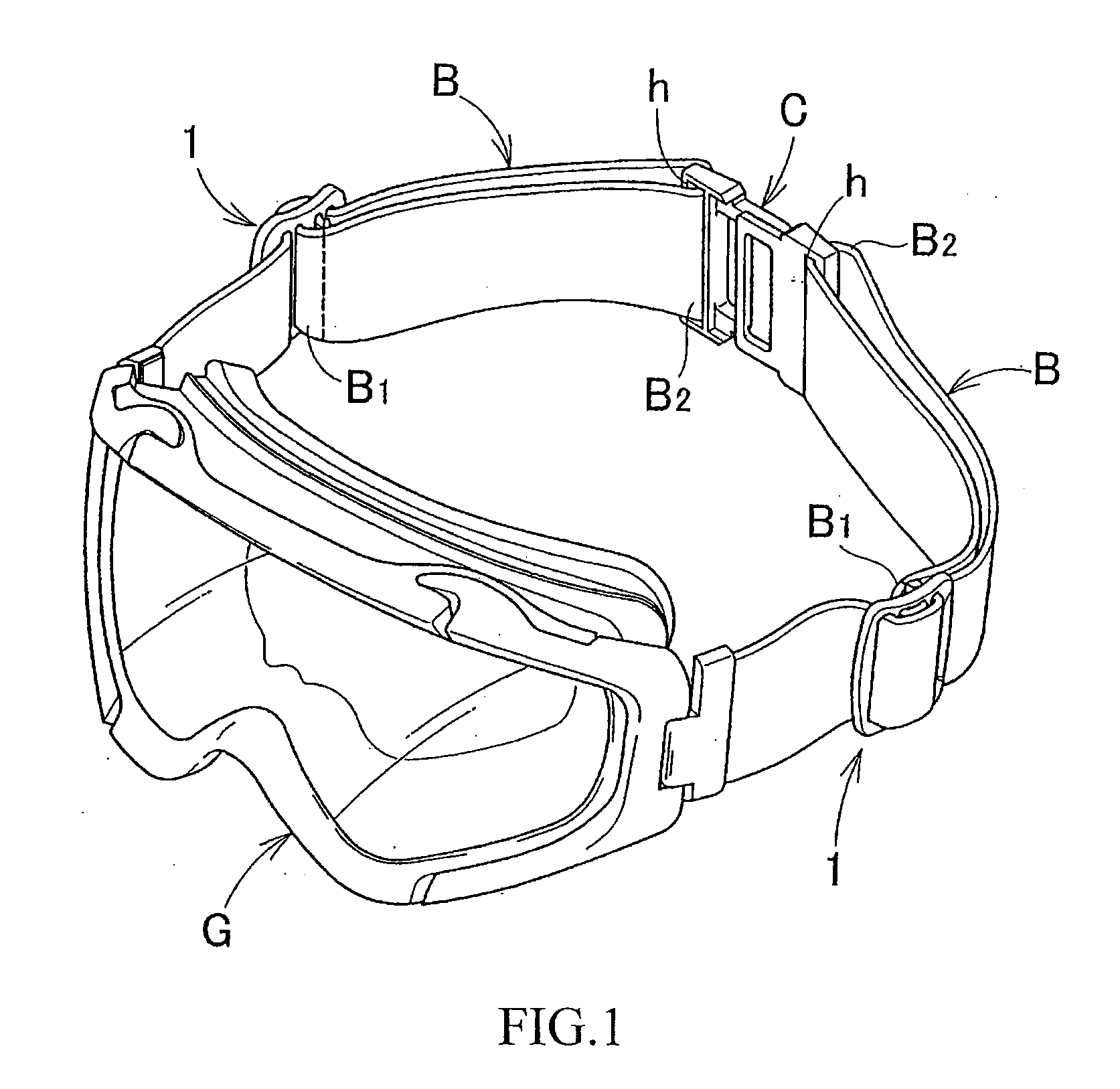
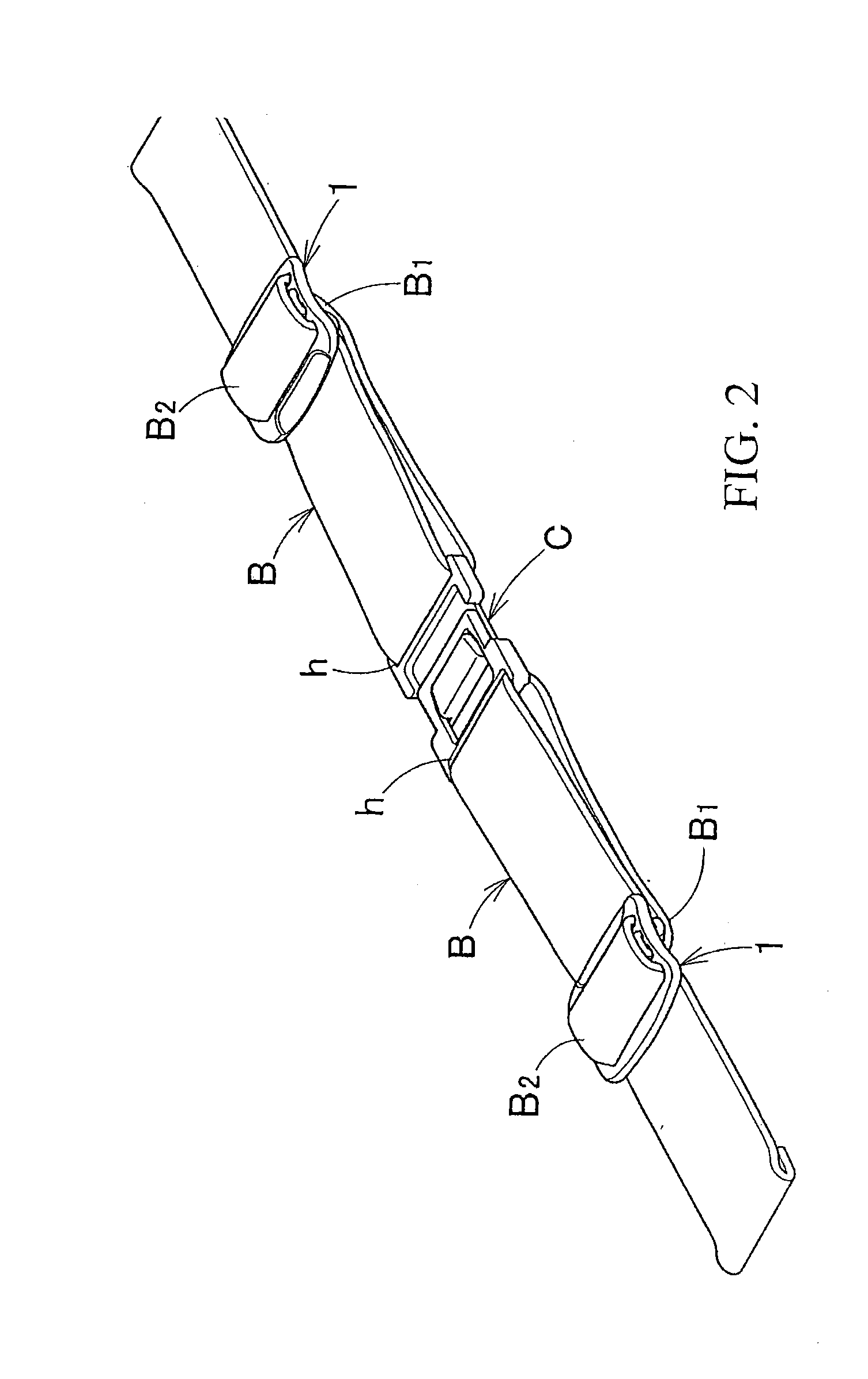
[0036]The belt length adjuster of the present invention is devised to be used with a wearing belt for goggles G and the like as shown in FIGS. 1 and 2, and enables adjustment of the length of the belt used therewith.

[0037]The wearing belt includes a pair of belt members B each of which has one end part B1 and the other end side B2. The one end part B1 of each belt member is supported by a belt length adjuster of the present invention. The other end side B2 of each belt member is inserted into a through hole h of a connector C. Each of the belt members is folded back at the through hole h and then inserted through the belt length adjuster of the present invention, drawn out therefrom, and connected to one side end of the goggles G. Both side ends of the goggles receive the other end sides B2 of the pair of the belt members B, respe...


PUM


Abstract

A belt length adjuster includes a frame body with two outer frames and two connecting frames, and a support frame provided between the two outer frames and stretching to and between the two connecting frames. The support frame supports one end part of the belt member to be used with the belt length adjuster. Two inner frames are respectively provided between the support frame and the respective outer frames and stretching to and between the two connecting frames. The support frame and the respective inner frames provide first insertion spaces into which the one end part of the belt member is inserted, while the respective inner frames and the respective outer frames provide second insertion spaces into which the other side of the belt member is inserted. Furthermore the one end part of the belt member is easily attached to the frame body.

Description

FIELD OF THE INVENTION[0001]The present invention relates to a belt length adjuster suitable for a wearing belt for goggles such as snow goggles, motor sport goggles, swimming goggles, safety protection goggles.BACKGROUND OF THE INVENTION[0002]An adjuster shown in FIG. 12 has been generally known as a belt length adjuster of this type. The adjuster includes a frame body 11, which has a substantially square shape with both side frames 11a and 11a and both connecting frames thereof 11b and 11b, and a support frame 12 for belt provided at a substantially central part of the inside of the frame body 11. An insertion space S is formed in both sides of the support frame 12, and a serrations or knurls 13 for slip prevention are provided on an inner side of each of both side frames 11a and 11a as desired.[0003]The above-described belt length adjuster is used as shown in FIGS. 13 to 15. One end part of a belt B for goggles and the like is attached on the support frame 12, and the other end s...

Claims


Application Information

Patent Timeline
Patent Type & Authority Applications(United States)
IPC IPC(8): F16B2/02
CPCY10T24/44017A44B11/04
Inventor SHINYA, MAKOTOTSUNASHIMA, KEIKO
Owner SWANS
Why Eureka
Try Eureka