Traveling wave distance measurement device based on passive magnetooptic glass current transformer principle

A technology of traveling wave ranging device and current transformer, which is applied in the direction of fault location, etc., can solve problems such as incorrectness, limitation of the flexibility of the ranging device, and inability to measure ranging results, and achieve the effect of improving reliability

Inactive Publication Date: 2012-01-18
CHINA ELECTRIC POWER RES INST +1
View PDF4 Cites 12 Cited by
  • Summary
  • Abstract
  • Description
  • Claims
  • Application Information

AI Technical Summary

Problems solved by technology

Due to the adoption of the serial transmission mechanism, the sampling time interval cannot be greater than the completion time of one serial sampling value transmission, which makes the current sampling frequency of this mode basically 500kHz; in addition, digital signals are prone to errors during high-speed serial transmission. Code, making the entire sampled value data invalid, if a sampled value transmission error occurs at the moment of failure, it may lead to inability to measure the distance or the result of the distance measurement is incorrect
The sampling frequency is independently controlled by the transformer, so that the distance measuring device cannot adjust its own sampling frequency, which limits the flexibility of the distance measuring device

Method used


Image

  • Traveling wave distance measurement device based on passive magnetooptic glass current transformer principle
  • Traveling wave distance measurement device based on passive magnetooptic glass current transformer principle
  • Traveling wave distance measurement device based on passive magnetooptic glass current transformer principle

Examples


Embodiment Construction

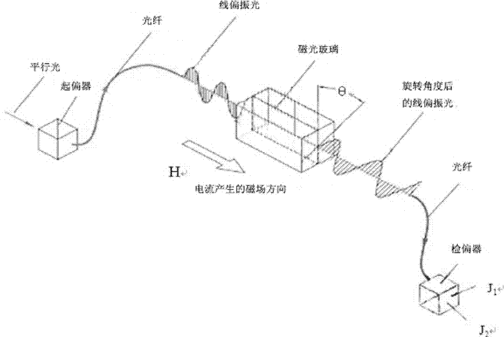
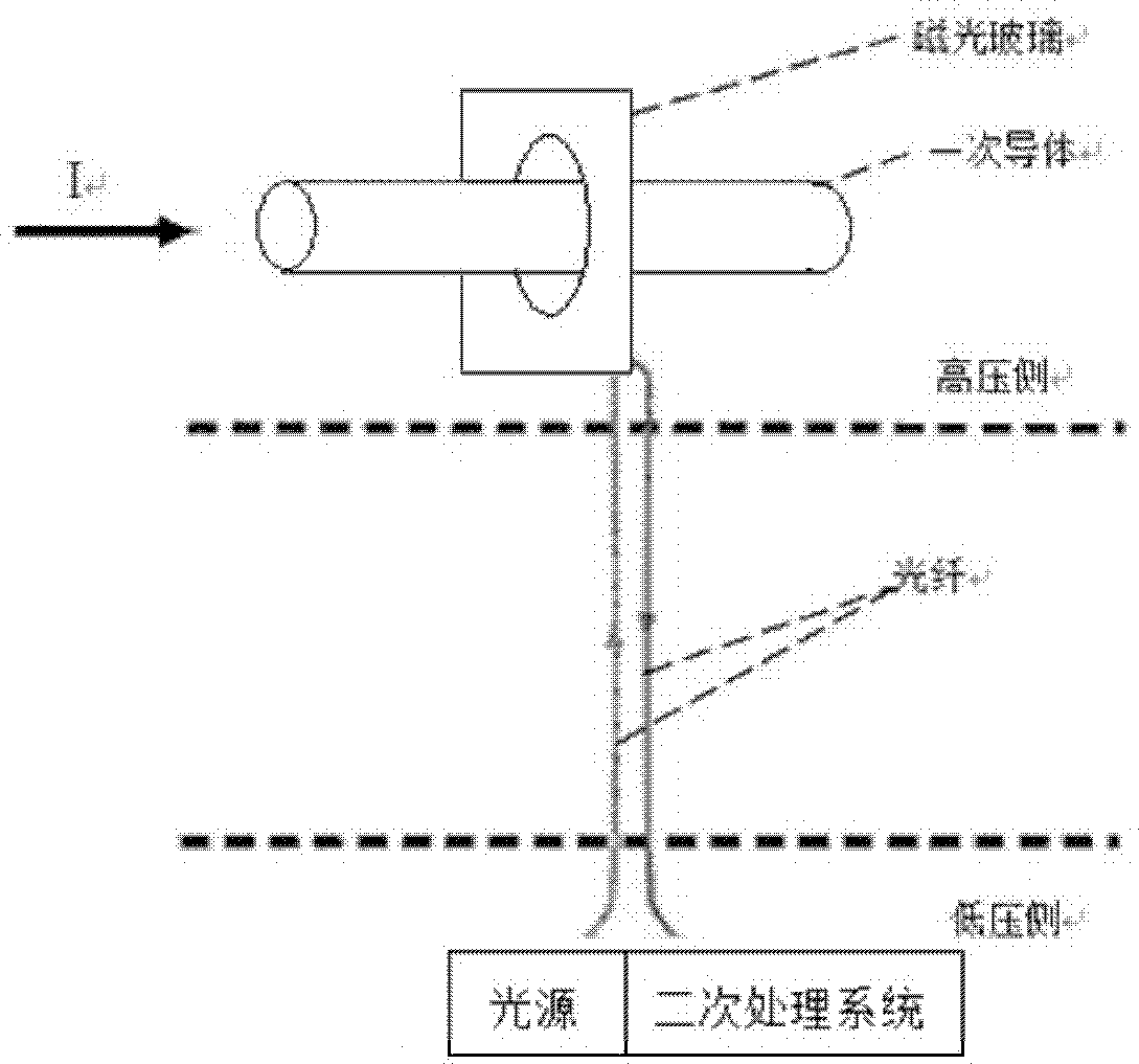
[0026] Such as figure 1 As shown, the optical glass current transformer is based on the Faraday effect. When a beam of linearly polarized light passes through a magneto-optical material placed in a magnetic field, the polarization plane of the linearly polarized light will occur linearly with the magnitude of the magnetic field parallel to the direction of the light. rotate. Such as figure 2 As shown, by measuring the rotation angle of the polarization plane of linearly polarized light around the current-carrying conductor, the current value in the conductor can be measured indirectly.

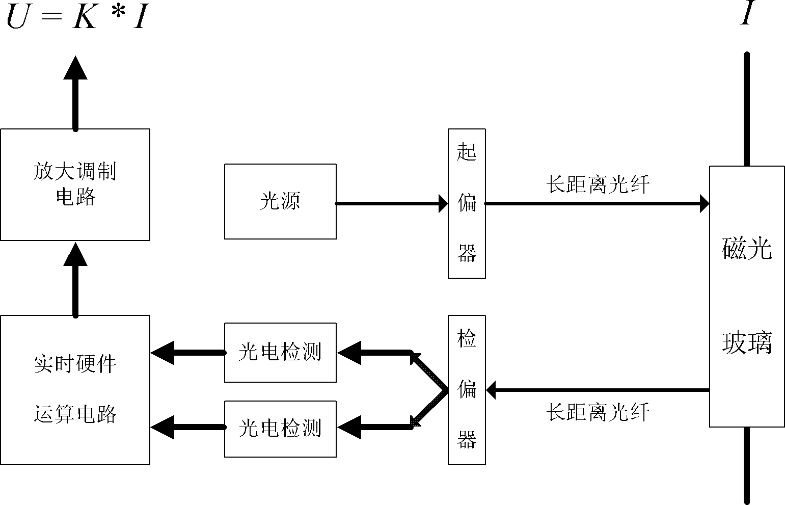
[0027] Implementation method: such as image 3 As shown, we use a pulse current to drive a GaAs double heterostructure light-emitting diode (LED) as a light source, and the light emitted by it is coupled into a long-distance multimode fiber. The pulse current is automatically adjustable from 20 to 100mA. The DC output signal is fed back to the LED drive source, and its current is automatic...


PUM


Abstract

The invention relates to a traveling wave distance measurement device based on a passive magnetooptic glass current transformer principle. A small voltage signal reflecting primary side current amplitude of a transmission line is obtained by adopting a passive magnetooptic glass electronic current transformer, and a high-speed acquiring circuit is controlled by a CPLD (Complex Programmable Logic Device) for recording and sampling 625KHz travelling wave data and starting the sampling of 20KHz criterion data. When the transmission line fails, the travelling wave distance measurement device judges whether the transmission line fails through the sampled 20KHz data, and controls a 625KHz high-speed sampling part to completely record high-speed sampled data comprising travelling signals and sends data to a background computer through communication, and the background computer automatically computes and recognizes a failed travelling wave head through a wavelet algorithm after obtaining dual-end circuit data, and realizes failure location of the transmission line according to different moments of the wave head arriving at a dual-end bus.

Description

technical field [0001] The invention belongs to the field of electric power system automation, specifically relates to a transmission line fault location technology, and proposes a traveling wave ranging device based on the principle of a passive magneto-optical glass current transformer. Background technique [0002] After the transmission line fails, even if the reclosure is successful, line inspectors are required to find the fault point, and judge whether the line can continue to operate or whether it needs to be powered off for maintenance according to the degree of damage caused by the fault, so as to eliminate hidden dangers. Therefore, quickly finding the fault point after the line fault becomes a key technology to ensure the safe and stable operation of the power grid. [0003] At present, digital substation technology has become the future development direction. Digital substations use low-power, digital new transformers to replace conventional ferromagnetic trans...

Claims


Application Information

Patent Timeline
Patent Type & Authority Applications(China)
IPC IPC(8): G01R31/08
Inventor 李冰覃剑郭宁明申仲涛王冬青宋合志刘润花李刚鹿洪刚汪一王化鹏
Owner CHINA ELECTRIC POWER RES INST
Why Eureka
Try Eureka