
Optical device with increased depth of field

a technology of optical devices and depth of field, which is applied in the field of optical devices, can solve the problems of loss of resolution and contrast, reduced image brightness, and limited field depth,

Inactive Publication Date: 2009-09-08
LEICA INSTR SINGAPORE PTE
View PDF12 Cites 1 Cited by
  • Summary
  • Abstract
  • Description
  • Claims
  • Application Information

AI Technical Summary

Benefits of technology

The present invention provides an optical device that can change the depth of field or the effective focal length of the main objective without the limitations of existing methods. This is achieved by using a special optical device described herein.

Problems solved by technology

In most optical devices the depth of field, i.e. the region in which one or more specimen points located on the optical axis are imaged in focus at the same time, is very limited.
The second possibility for increasing depth of field, by making the aperture smaller, results in a decrease in image brightness and a loss of resolution and contrast.

Method used


Image

  • Optical device with increased depth of field
  • Optical device with increased depth of field
  • Optical device with increased depth of field

Examples


Embodiment Construction

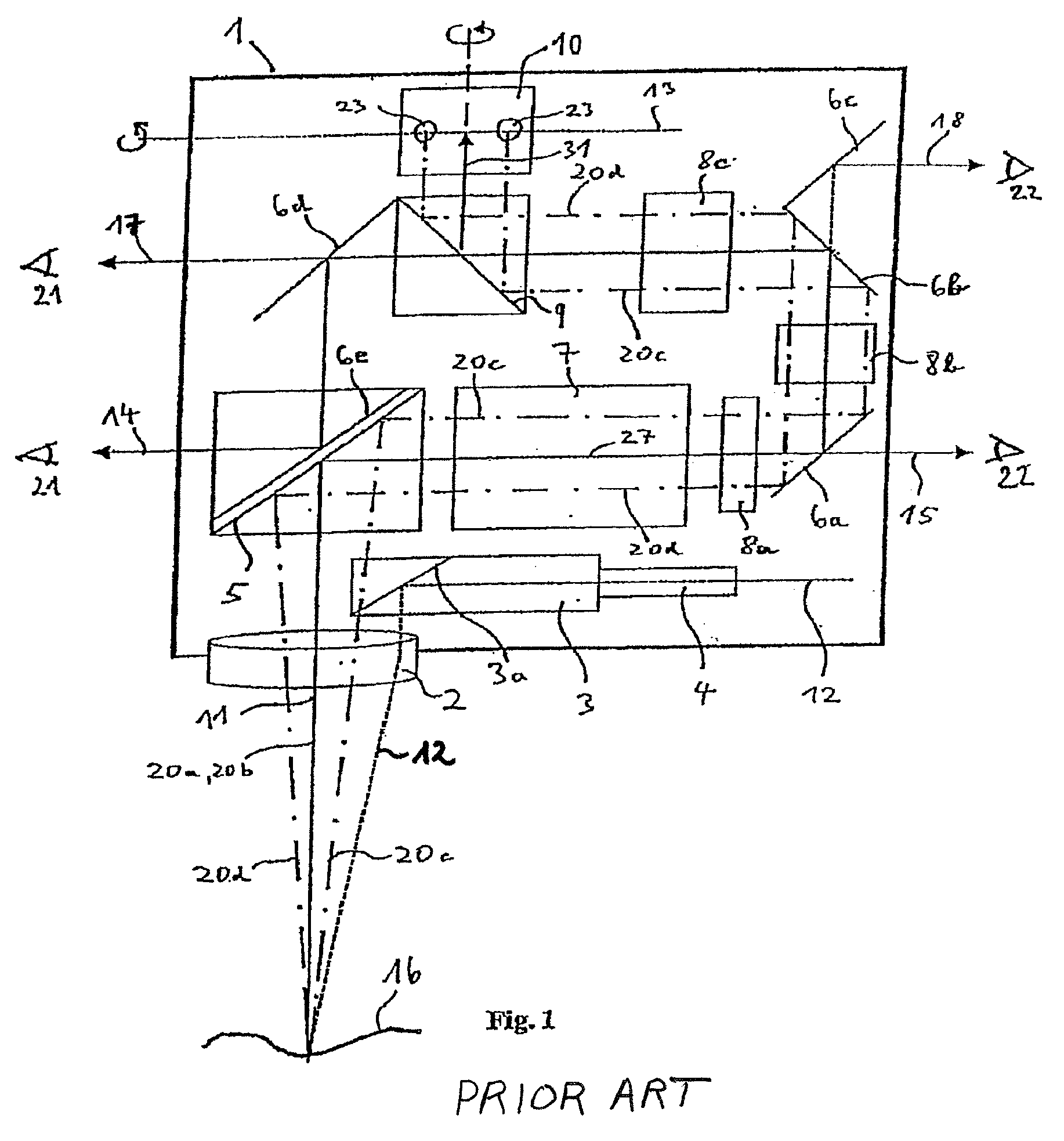
[0026]FIG. 1 shows an embodiment of a stereomicroscope according to DE 102 55 960 A1 (corresponding to U.S. Pat. No. 7,206,127) that will be explained briefly below. A schematically depicted microscope body of a stereomicroscope is labeled 1 in its entirety. The stereoscopic axes are located behind one another as depicted in FIG. 1, so that only one axis is visible. The stereomicroscope depicted is, in particular, an opthalmologic microscope with which a specimen 16 is to be observed and examined. The stereomicroscope comprises, as essential optical components, a main objective 2, a zoom system 7, and an eyepiece system (not depicted).

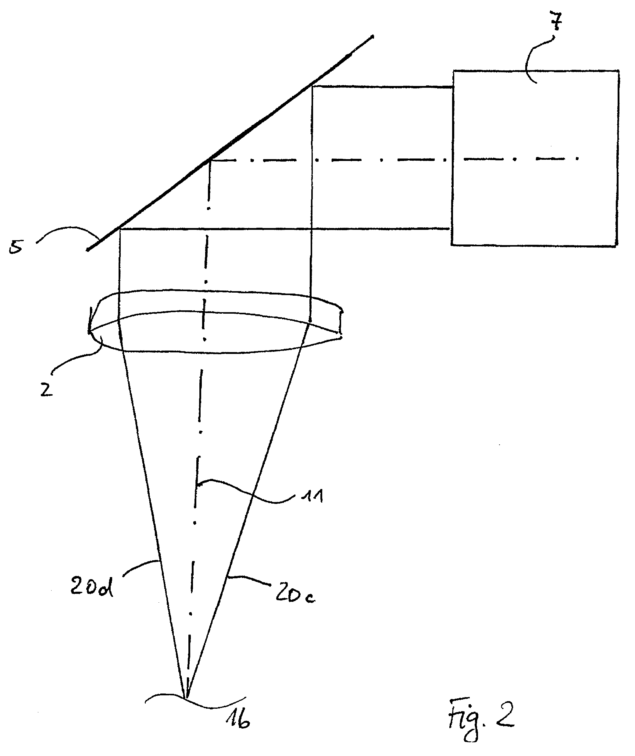
[0027]A first deflection element 5 is provided between main objective 2 and zoom system 7. Provided behind zoom system 7 are further deflection elements 6a, 6b, 6c, 6d, 6e, 9, and 10, as well as additional optical components 8a to 8c whose function will be explained later on.

[0028]The number 3 designates an illumination unit that directs light, made av...


PUM


Abstract

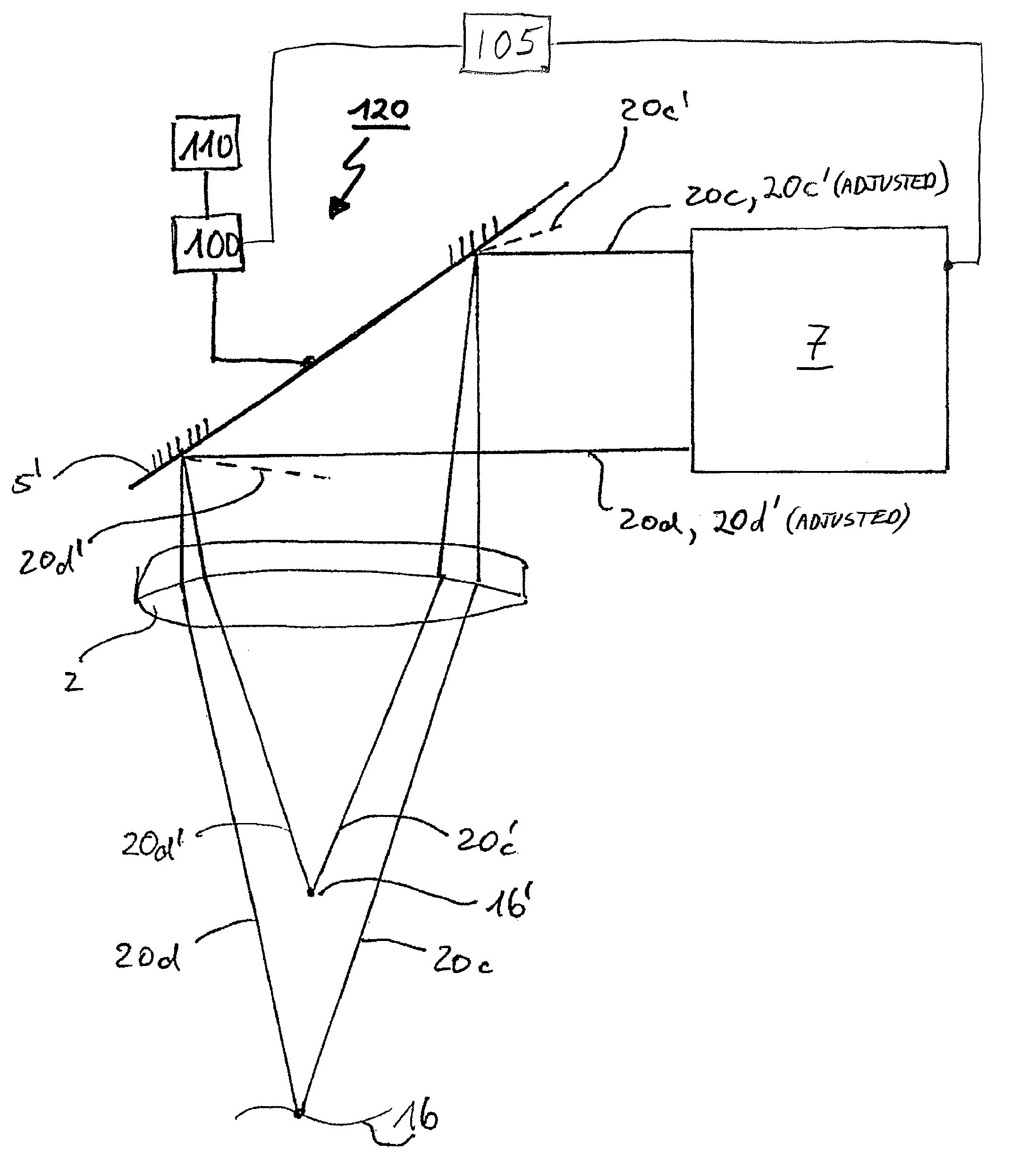
An optical device for imaging a specimen (16) has a main objective (2) and a device (120) for modifying depth of field, the device (120) representing a micromirror array (5′) having micromirrors (50) that are individually controllable and adjustable as to their spatial orientation. In addition to the increase in depth of field, a variable objective can also be produced. The invention is particularly suitable for use in a microscope where deflection of the observation beam path is present.

Description

CROSS REFERENCE TO RELATED APPLICATIONS[0001]This application claims priority of German patent application no. 10 2006 025 149.0 filed May 30, 2006 which is incorporated by reference herein.FIELD OF THE INVENTION[0002]The invention relates to an optical device, in particular to a stereomicroscope, for imaging a specimen, having a main objective and a device for modifying depth of field or the effective focal length of the main objective of the optical device.BACKGROUND OF THE INVENTION[0003]Microscopes comprise at least two imaging optical elements, namely a main objective and an eyepiece. All optical observation devices possess, in principle, the same fundamental construction. The two optical elements (objective and eyepiece) form an overall system that defines the potential magnification range as well as the depth of field. In most optical devices the depth of field, i.e. the region in which one or more specimen points located on the optical axis are imaged in focus at the same ti...

Claims


Application Information

Patent Timeline
Patent Type & Authority Patents(United States)
IPC IPC(8): G02B21/00G02B5/08G02B30/60
CPCA61B19/52G02B26/0833G02B21/22G02B21/025A61B19/5223A61B90/36A61B90/20
Inventor SANDER, ULRICH
Owner LEICA INSTR SINGAPORE PTE
Learn More