
Intelligent vision detection device and detection method

A vision detection and intelligent technology, applied in retinoscopes, refractometers, etc., can solve the problems of poor measurement accuracy of vision chart detection method, large size of computer refractometers, and mastery of eye degree, etc. High accuracy and the effect of improving measurement accuracy

Inactive Publication Date: 2020-01-31
ZHEJIANG UNIV
View PDF5 Cites 1 Cited by
  • Summary
  • Abstract
  • Description
  • Claims
  • Application Information

AI Technical Summary

Problems solved by technology

At present, traditional methods are still used for visual acuity testing, such as eye charts and computer refractometers, etc., but the measurement accuracy of the eye chart test method is poor and it is not easy to carry. The computer refractor is bulky, complicated to use and requires professional Institutions, so patients cannot conveniently and timely grasp the change trend of eye degree and carry out appropriate medical intervention

Method used


Image

  • Intelligent vision detection device and detection method
  • Intelligent vision detection device and detection method
  • Intelligent vision detection device and detection method

Examples


Embodiment 1

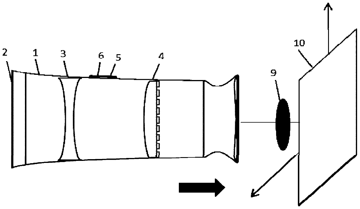
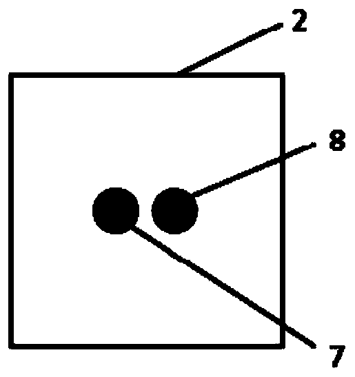
[0038]In this intelligent vision detection device, the concave lens 3 adopted by the device is crown glass, its thickness is 2mm, and the section radius perpendicular to the optical axis is 6mm, and the curvature radii of the two surfaces of the concave lens 3 are equal, which is 45mm; The hybrid lens 4 thickness that adopts is 4mm, and the section radius perpendicular to the optical axis is 6mm, and described hybrid lens 4 is made of refraction lens and binary diffraction structure, and described refraction lens is plano-convex lens, and the first surface of described plano-convex lens It is a convex surface with a radius of curvature of 60mm, and the second surface is a plane. The binary diffractive structure is processed by photolithography and injection molding on the second surface of the refracting lens; the binary diffractive structure is a concave microstructure, and the size of the concave microstructure is 80 line pairs / mm. The device includes a casing 1, a liquid cr...

Embodiment 2

[0041] In this intelligent vision detection device, the concave lens used in the device is made of resin material, its thickness is 2mm, and the radius of the section perpendicular to the optical axis is 6mm, and the curvature radii of the two surfaces of the concave lens are equal, which is 55mm; The thickness of the lens is 4 mm, and the radius of the section perpendicular to the optical axis is 10 mm. The hybrid lens is composed of a refractive lens and a binary diffraction structure. The refractive lens is a plano-convex lens, and the first surface of the plano-convex lens has a radius of curvature of 70 mm. The convex surface, the second surface is a plane, and the binary diffractive structure is processed by photolithography on the second surface of the refracting lens and injection molded; the binary diffractive structure is a concave microstructure, and the size of the concave microstructure is 100 line pairs / mm . The device includes a casing 1, a liquid crystal displa...


PUM


Abstract

The present invention discloses an intelligent vision detection device and method, and belongs to the fields of optical system design and manufacture, binary optical imaging, geometric optics and optical aberration. The device comprises a shell body, a liquid crystal display screen, a concave lens, a hybrid lens, a power supply, a driving chip, a first key, a second key and a Bluetooth transmission module. The liquid crystal display screen, the concave lens and the hybrid lens are sequentially fixed in the shell body; the first key and the second key are fixed on an outer side of the shell body, and the power supply, the driving chip and the Bluetooth transmission module are fixed on an inner side of the shell body; and the power supply is connected with the driving chip, and the driving chip is respectively connected with the liquid crystal display screen, the Bluetooth transmission module, the first key and the second key. Portability of vision measuring devices is greatly improved and the intelligent vision detection device has characteristics of high measuring precision, simple operation and also strong real-time property.

Description

technical field [0001] The invention belongs to the fields of optical system design and manufacture, binary optical imaging, geometric optics and aberration, and in particular relates to an intelligent vision detection device and a detection method. Background technique [0002] In China, about 450 million people wear glasses, the myopia rate of primary school students is 30%, and that of middle school students is as high as 80%, and the number of people wearing glasses is still increasing year by year. Teenagers are under heavy study pressure, and their eyes are always in a state of fatigue, which is prone to true myopia. Therefore, it is necessary to detect changes in eye power in a timely manner. At present, traditional methods are still used for visual acuity testing, such as eye charts and computer refractometers, etc., but the measurement accuracy of the eye chart test method is poor and it is not easy to carry. Institutions, so patients cannot easily and timely grasp...

Claims


Application Information

Patent Timeline
Patent Type & Authority Applications(China)
IPC IPC(8): A61B3/103
CPCA61B3/103
Inventor 汪凯巍颜冉白剑于红雷张豫
Owner ZHEJIANG UNIV
Learn More