Measuring brace and arrangement and method for determining the forward angle of inclination of a spectacle frame

a technology of measuring brace and forward angle, which is applied in the field of measuring brace, can solve the problems of measuring errors, measuring brace falling from the spectacle frame with a slight movement of the test person,

Active Publication Date: 2009-09-15
CARL ZEISS VISION INT GMBH
View PDF11 Cites 12 Cited by
  • Summary
  • Abstract
  • Description
  • Claims
  • Application Information

AI Technical Summary

Benefits of technology

[0007]It is an object of the invention to provide an alternative measuring brace for video centering systems which makes possible, in a simple and space-saving manner, the determination of the forward inclination of the spectacle frame for the habitual posture of the test person.

Problems solved by technology

The disadvantage here is that the measuring brace can fall from the spectacle frame with a slight movement of the test person.
Furthermore, two rods are in the field of view of the test person which, in turn, is disturbing and can lead to measuring errors.

Method used


Image

  • Measuring brace and arrangement and method for determining the forward angle of inclination of a spectacle frame
  • Measuring brace and arrangement and method for determining the forward angle of inclination of a spectacle frame
  • Measuring brace and arrangement and method for determining the forward angle of inclination of a spectacle frame

Examples


Embodiment Construction

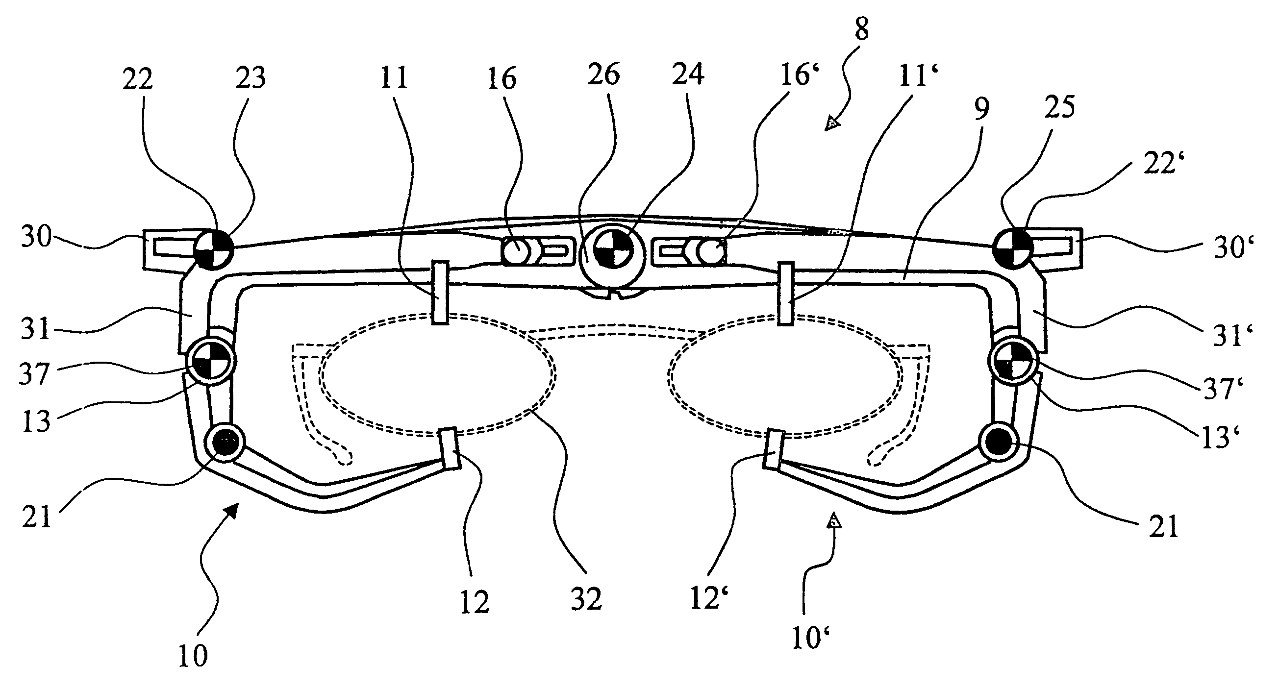
[0087]Conventionally, the optical centering of the spectacle lenses takes place in that one places a measuring brace on a spectacle frame (without lenses) and views the head of the test person with a video unit from a long distance, for example, a distance of 5 m, and measures the relevant angles in the video images. The test person is, for example, a customer and the spectacle frame is anatomically adapted and this takes place in the office of an optometrist or an ophthalmologist.

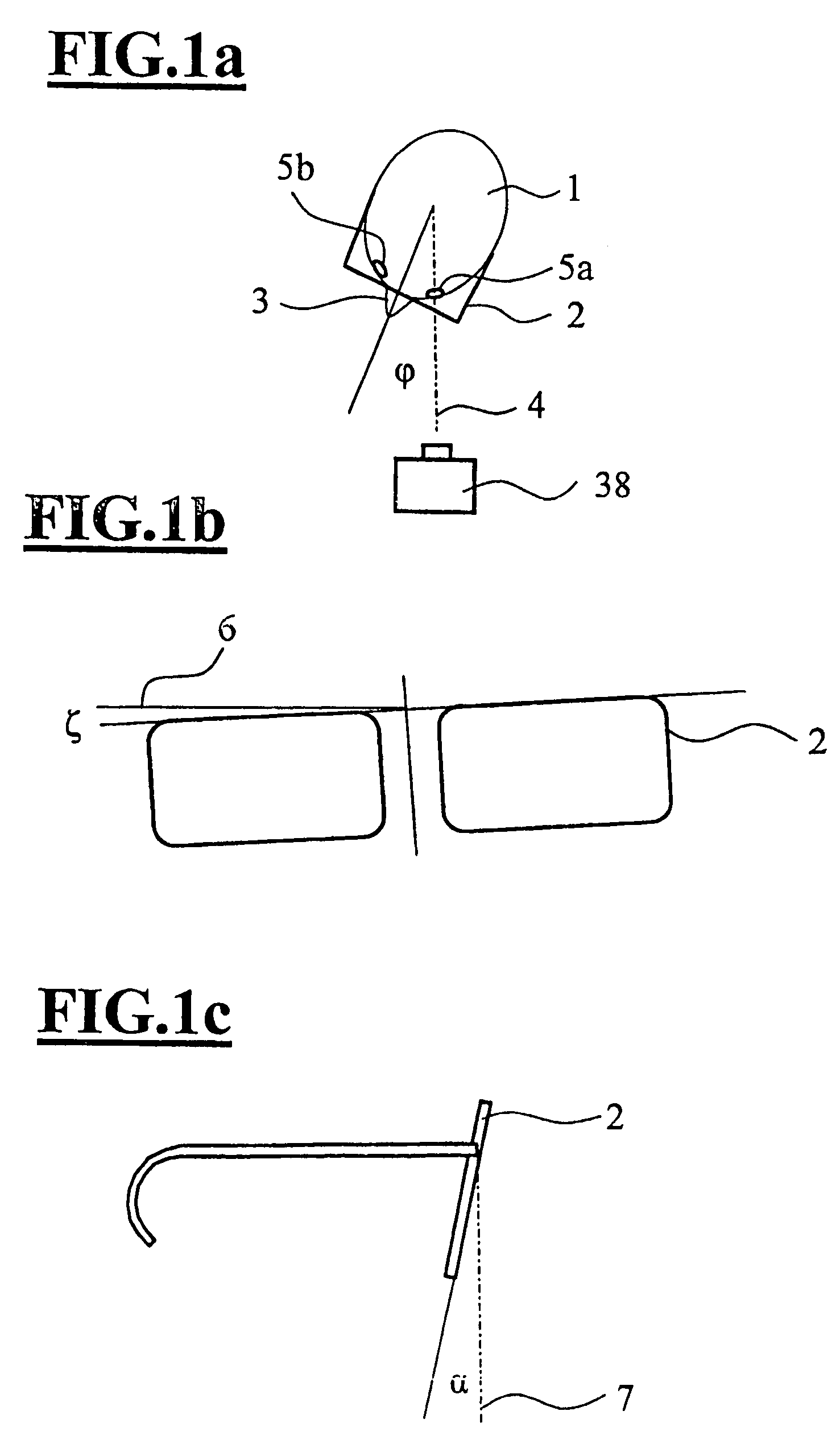
[0088]In the simplest case, photo images can be made. The test person, for example, a customer, looks in the direction of a camera and a picture recording of the face is made with the spectacle frame and the measuring brace.

[0089]During the measurement, the test person usually aligns toward a fixation mark of a video centering system. In the ideal case, the test person stands exactly parallel to the optical axis of the optical imaging system, for example, a video camera. Often, the case occurs that the tes...


PUM


Abstract

A measuring brace is removably fastened to a spectacle frame. The measuring brace has a traverse and two legs. A front face of the measuring brace is provided with at least three front target marks for measuring the forward angle (α) of a spectacle frame to be measured. At least one of the front target marks is disposed spatially offset relative to the at least two other front target marks, essentially perpendicular to the front face of the measuring brace. The measuring brace has coupled clamping elements provided for fastening the spectacle frame (32). In addition, a measuring brace is suggested which is removably fixed to a spectacle frame and in which at least three lateral target marks (27, 27′, 28, 28′, 29, 29′) are provided for measuring an angle of twist (ε). The invention also relates to an arrangement and a method for determining the forward tilt angle (α) and the angle of twist (ε) of a spectacle frame.

Description

CROSS REFERENCE TO RELATED APPLICATIONS[0001]This application is a continuation application of international patent application PCT / EP 2005 / 009949, filed Sep. 15, 2005, and claiming priority from German application 10 2004 045 012.9, filed Sep. 15, 2004, and the entire content of both applications is incorporated herein by reference.FIELD OF THE INVENTION[0002]The invention relates to a measuring brace for the releasable attachment to a spectacle frame. In addition, the invention is directed to a measuring brace for the releasable attachment to a spectacle frame with a traverse and two legs. The forward side of the measuring brace has at least three front target marks for a measurement of the forward inclination angle (α) of a spectacle frame to be measured and at least one of the front target marks is arranged essentially spatially offset perpendicular to the forward side of the measuring brace relative to the at least two other front target marks. The invention further relates to ...

Claims


Application Information

Patent Timeline
Patent Type & Authority Patents(United States)
IPC IPC(8): A61B3/10A61B3/00
CPCG02C13/005G02C13/003
Inventor KUBITZA, MATTHIAS
Owner CARL ZEISS VISION INT GMBH
Why Eureka
Try Eureka