Removable grate

a grate and grate technology, applied in the field of two-part grate assembly, can solve the problems of time-consuming, difficult, expensive, etc., and achieve the effect of reducing the cost of grate assembly

Active Publication Date: 2009-09-15
ZURN INDS
View PDF38 Cites 19 Cited by
  • Summary
  • Abstract
  • Description
  • Claims
  • Application Information

AI Technical Summary

Benefits of technology

[0007]Generally, the present invention is directed to a two-part grate assembly for a channeled drain trough and, more particularly, to a grate assembly having a grate frame that is adapted to receive a removable grate section. Further, the present invention is directed to a grate frame having lugs with vertical projections extending therefrom that define securing recesses that assist in aligning and securing the grate frame atop a drain trough. Additionally, the present invention is directed to the use of an alignment bar that prevents the grate section from sliding out of operating position within the grate frame by restricting lateral movement of the grate section. Further, the present invention is directed to a method of providing a grate assembly for a channeled drain trough having a grate frame that is adapted to receive a removable grate section.
[0014]Further, an alignment bar that extends throughout the width of the grate frame is provided. The alignment bar engages the grate frame and the grate section to prevent lateral movement of the grate section secured within the grate frame when the alignment bar is removably received into the slots.

Problems solved by technology

However, there are many instances where access to the interior of the trough is desirable and it can be difficult, expensive, and time-consuming to remove the desired section of the grate from the trough in order to access the interior of the trough.

Method used


Image

  • Removable grate
  • Removable grate
  • Removable grate

Examples


Embodiment Construction

[0036]For purposes of the description hereinafter, spatial or directional terms shall relate to the invention as it is oriented in the drawing figures. However, it is to be understood that the invention may assume various alternative variations, except where expressly specified to the contrary. It is also to be understood that the specific components illustrated in the attached drawings, and described in the following specification, are simply exemplary embodiments of the invention. Hence, specific dimensions and other physical characteristics related to the embodiments disclosed herein are not to be considered as limiting.

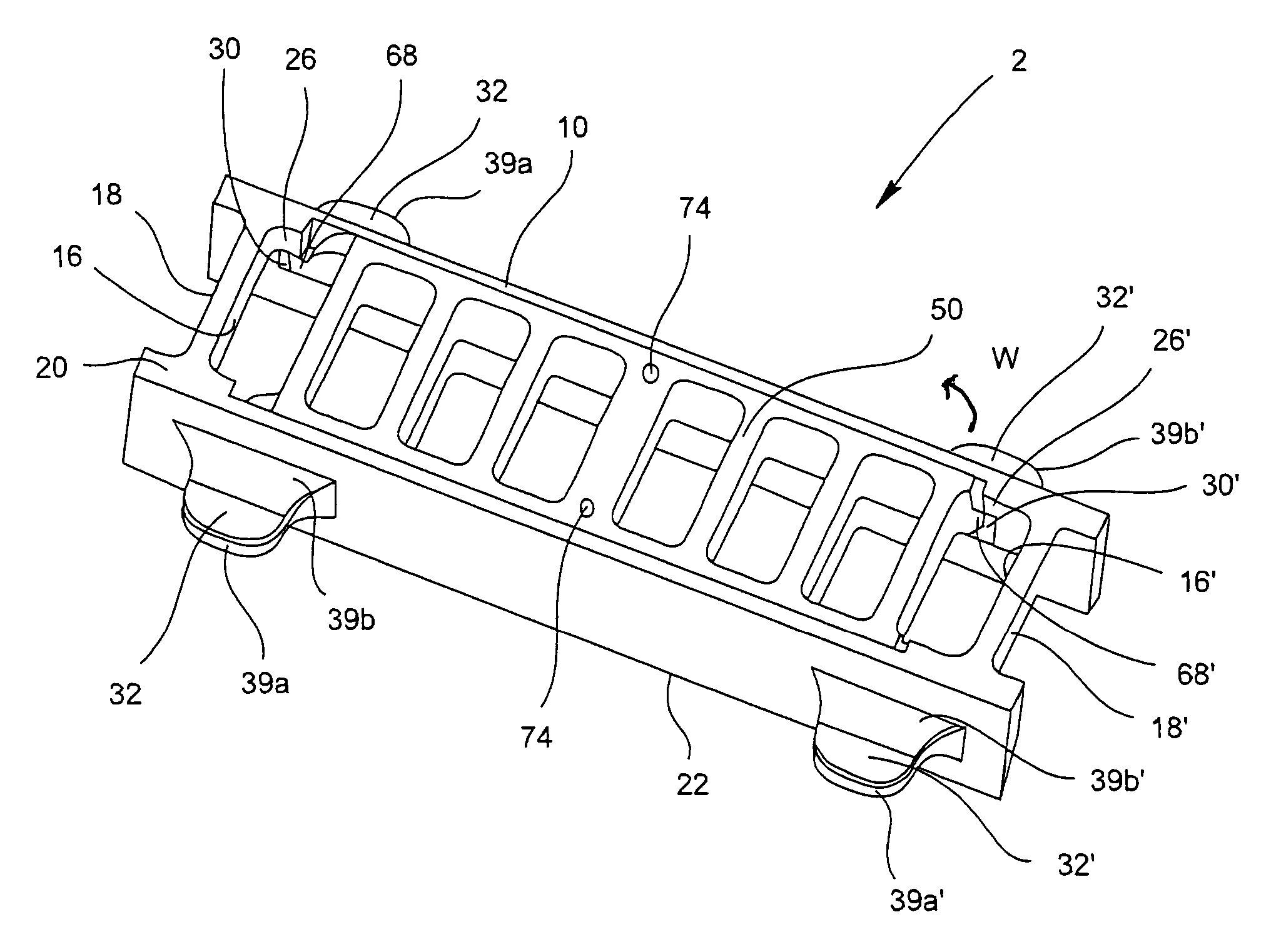
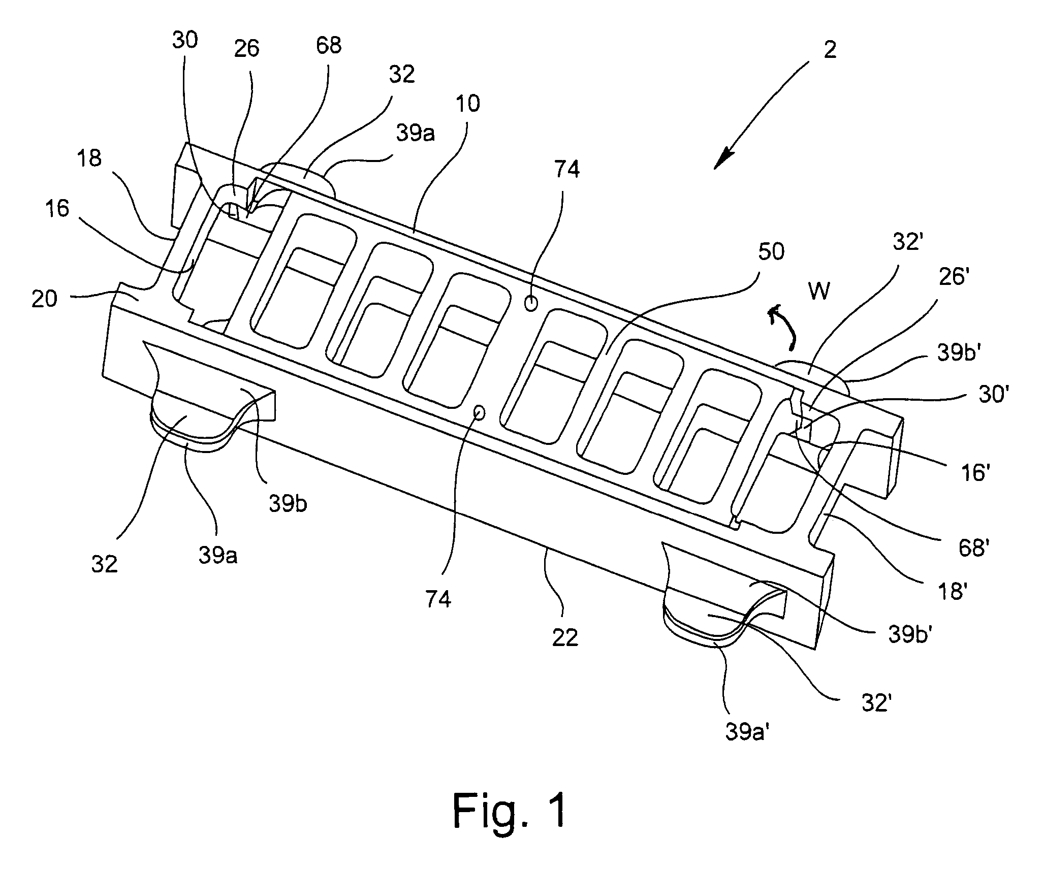
[0037]FIG. 1 shows a two-part grate assembly 2 according to the present invention. The two-part grate assembly 2 has a grate frame 10 adapted to receive a removable grate or grate section 50. The grate section 50 is removable and is slidably received by the grate frame 10. The grate frame 10 and grate section 50 may be manufactured out of cast iron, ductile iron, ...


PUM


Abstract

A two-part grate assembly for a channeled drain trough. The grate assembly has a grate frame that receives a removable grate section. The grate frame has lugs with vertical projections extending therefrom that define securing recesses that assist in aligning and securing the grate frame atop a drain trough. Additionally, the present invention is directed to the use of an alignment bar that prevents the grate section from sliding out of operating position within the grate frame by restricting lateral movement of the grate section. Further, the present invention is directed to a method of providing a grate assembly for a channeled drain trough having a grate frame that is adapted to receive a removable grate section.

Description

CROSS REFERENCE TO RELATED APPLICATION[0001]This application is based on Provisional Patent Application No. 60 / 794,377 filed Apr. 24, 2006, on which priority of this patent application is based, and which is hereby incorporated by reference in its entirety.BACKGROUND OF THE INVENTION.[0002]1. Field of the Invention[0003]The present invention relates generally to a two-part grate assembly for a channeled drain trough and, more particularly, to a grate assembly having a grate frame that is adapted to receive a removable grate section.[0004]2. Description of Related Art[0005]Channeled drains, such as trench drains, are utilized to transfer extensive amounts of liquid from one place to another and typically transport the liquid to a drainage sewer. Such drains are installed in the ground and secured within concrete. The drains are often U-shaped or V-shaped troughs and are usually installed adjacent to either roadways or buildings. To prevent injury to people and avoid debris entering t...

Claims


Application Information

Patent Timeline
Patent Type & Authority Patents(United States)
IPC IPC(8): E03F5/06
CPCE03F5/06E03F2005/065E03F2005/063
Inventor WROBLEWSKI, DOUGHIMES, KEVIN D.SLATER, PATRICKDALTON, DOUGLASECKLUND, DAVID A.SANFILIPPO, JOSEPH A.
Owner ZURN INDS
Why Eureka
Try Eureka