
Floating attachment linkage

a technology of attachment linkage and attachment, which is applied in the direction of mowers, agriculture tools and machines, and mowers, etc., can solve the problems of not allowing the pitch of the attachment to be set, and not allowing the attachment to floa

Inactive Publication Date: 2006-03-16
CLARK EQUIP CO INC
View PDF19 Cites 19 Cited by
  • Summary
  • Abstract
  • Description
  • Claims
  • Application Information

AI Technical Summary

Benefits of technology

[0003] The present invention includes a mower having a housing with an open bottom for mowing underneath the housing. A mower blade or blades are positioned within the housing and is driven by a motor mounted to the housing. A linkage assembly connects a prime mover to the mower housing where the prime mover moves the housing. The linkage assembly allows the housing to vertically move and rotationally move about an axis along a path of travel while limiting the lateral movement of the mower housing.

Problems solved by technology

However, the linkage that attaches the attachment to the prime mover typically does not allow the pitch of the attachment to be set prior to use and maintained during use even as the attachment travels over uneven terrain.
Additionally, linkages that mount attachments to prime movers in the prior art do not allow the attachment to float over the terrain by providing for vertical and rotational movement of the attachment.
Especially in the case of a mower, the inability of the mower to float about the terrain causes an uneven cutting which may provide a unsatisfactory result.

Method used


Image

  • Floating attachment linkage
  • Floating attachment linkage
  • Floating attachment linkage

Examples


Embodiment Construction

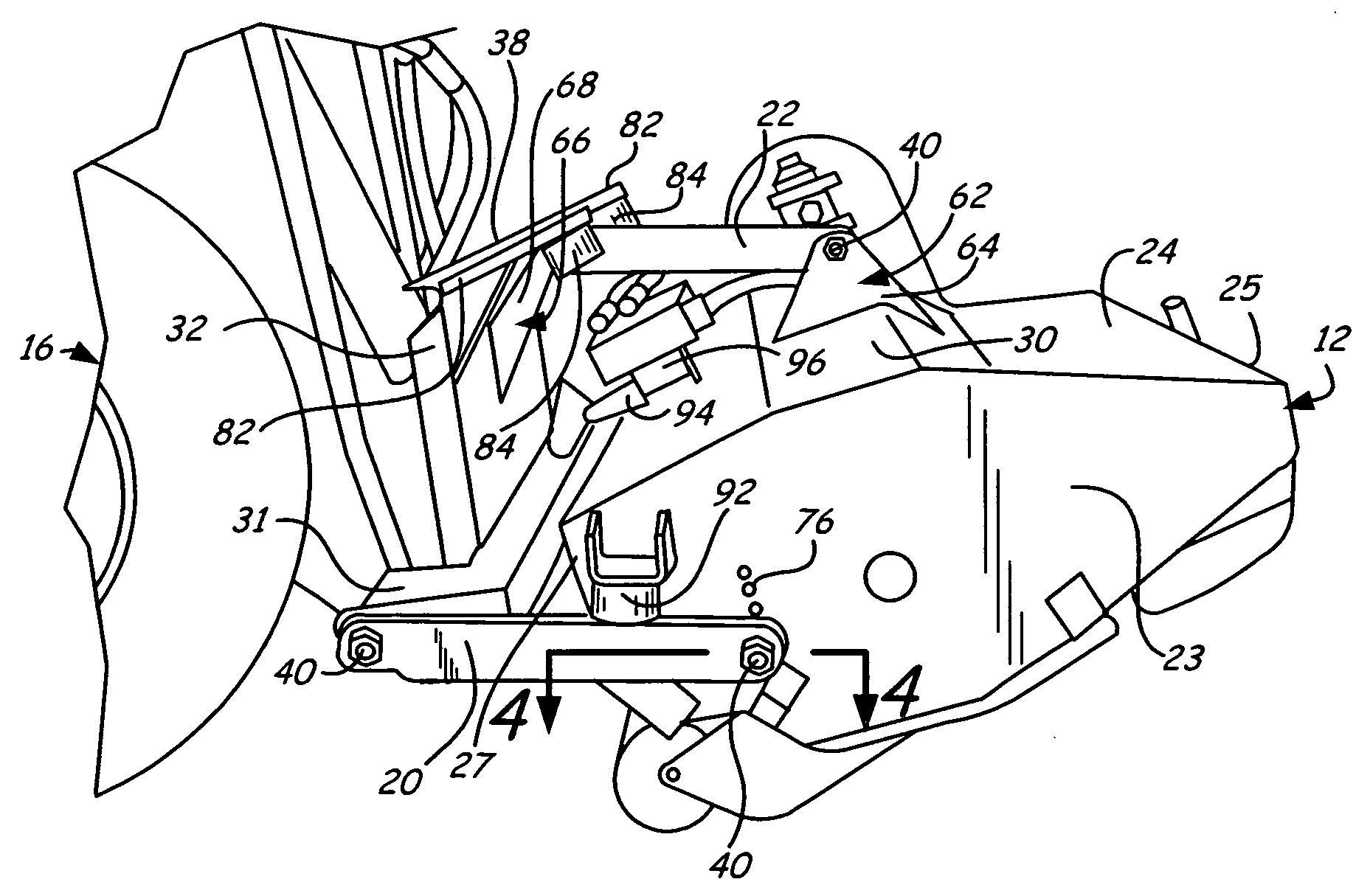
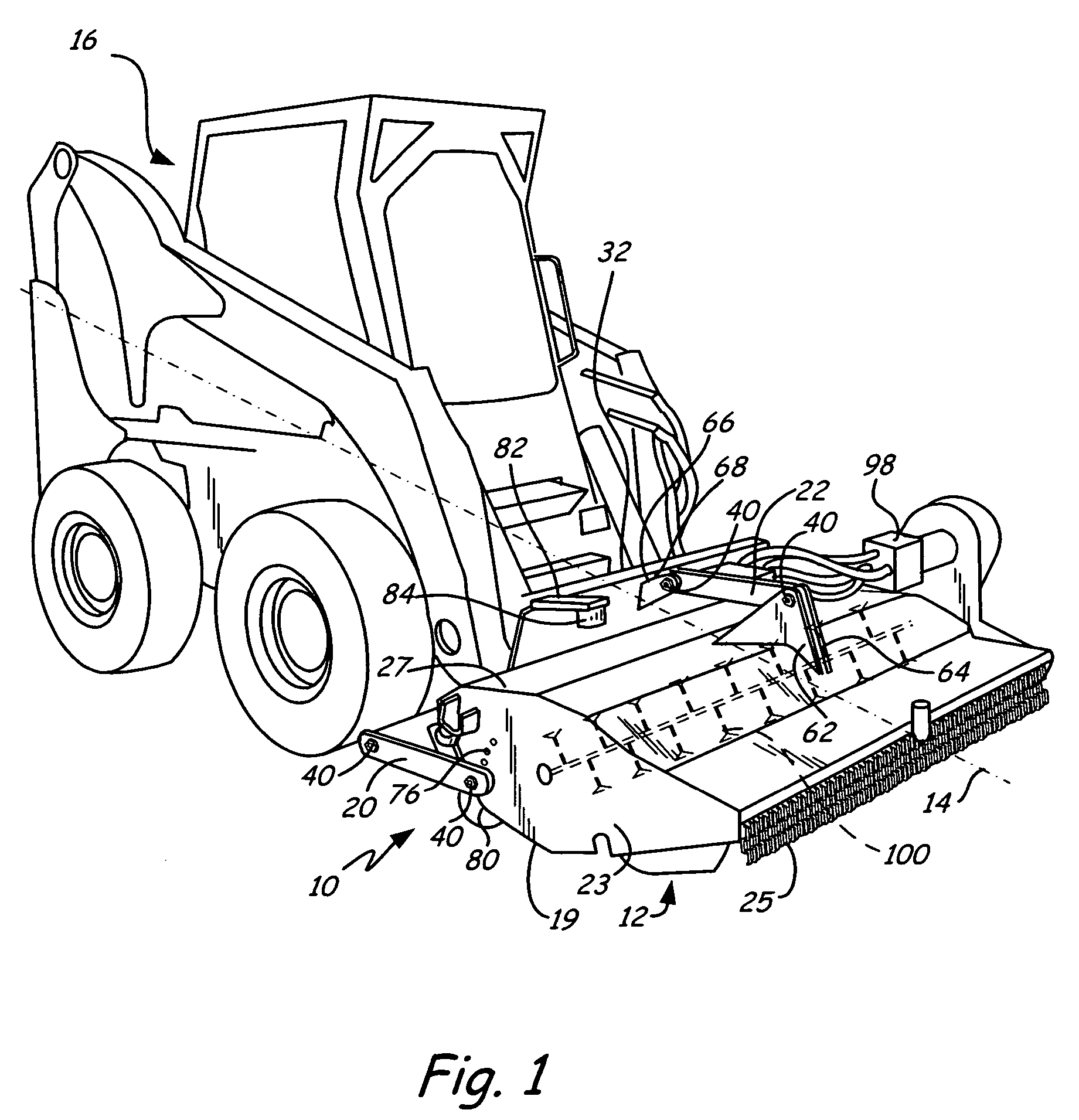
[0010] A linkage assembly of the present invention is generally illustrated at 10 in FIG. 1. The linkage assembly 10 attaches a flail mower 12 to a prime mover 16, such as a loader.

[0011] The linkage assembly 10 allows the flail mower 12 to move vertically and rotate about an axis 14 of movement along a forward path of travel while limiting the lateral movement of the flail mower 12 with respect to the loader 16. The linkage assembly 10 can also be used to mount other attachments besides a flail mower to the loader 16.

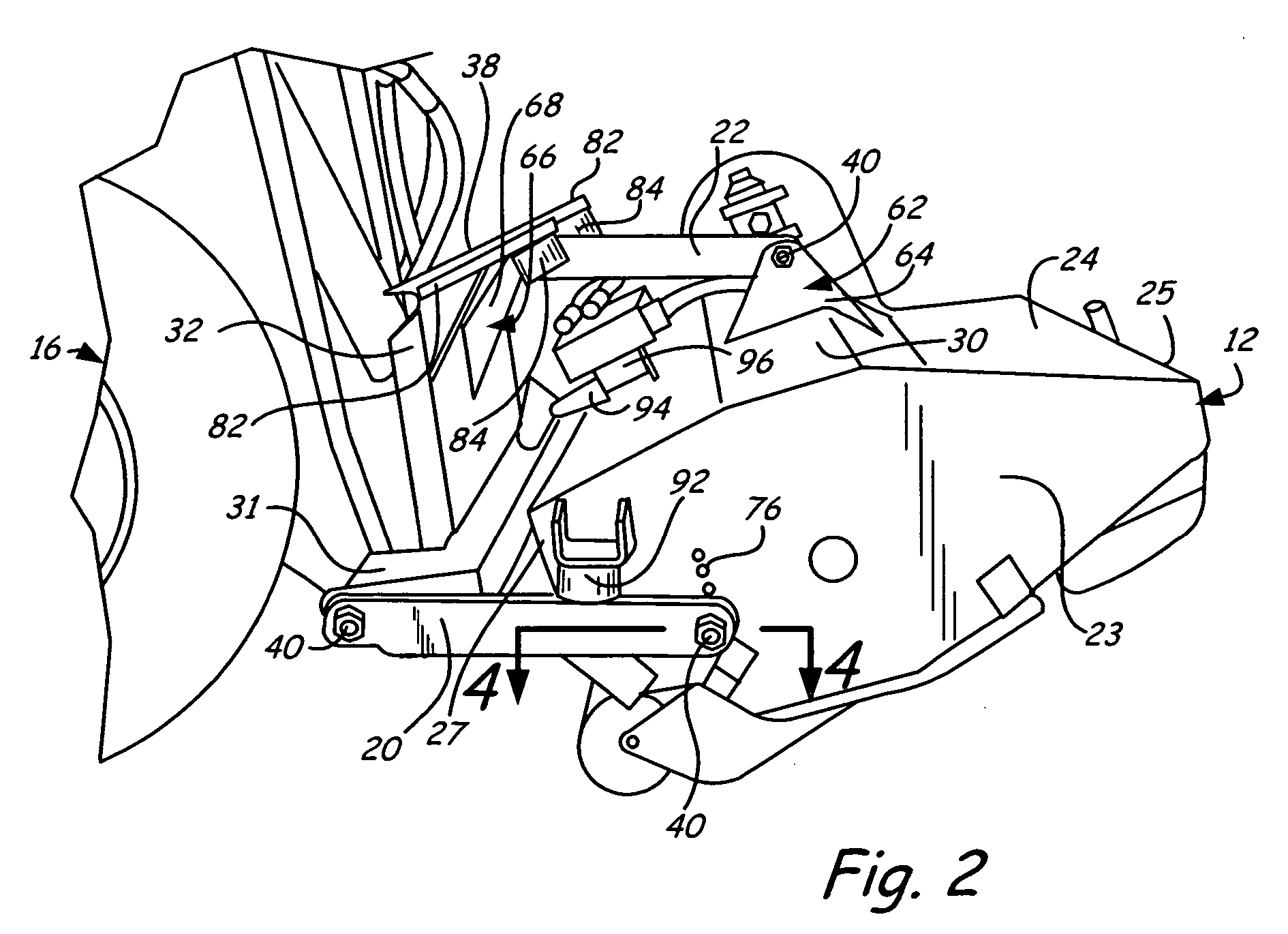
[0012] Referring to FIGS. 1-3, the linkage assembly 10 preferably includes three linkages generally parallelly aligned along the axis 14 of the forward path of travel. A left linkage 18 is attached to a left side panel 21 of flail mower housing 24 and proximate a lower left corner 33 of an attachment plate 32 that is mounted to the loader 16. A right linkage 20 is attached to a right side panel 23 of the flail mower housing 24 and also proximate a lower right corner ...


PUM


Abstract

A mower comprising a mower housing with an open bottom for mowing underneath the housing. A mower blade is positioned with the housing and is driven by a motor mounted to the housing. A linkage assembly attaches a prime mover to the housing and supports the mower relative to the prime mover wherein the linkage assembly provides vertical and rotational movement of the housing about an axis along a path of travel of the mower.

Description

BACKGROUND OF THE INVENTION [0001] The present invention relates to linkage assembly for mounting an attachment to a prime mover. In particular, the linkage assembly enables a pitch of the attachment to be initially set and maintained during operation while allowing for vertical movement and rotational movement of the attachment about an axis along a forward path of travel while restricting lateral movement of the attachment. [0002] Attachments, such as mowers, that are mounted to prime movers, such as skid steer loaders, are known in the art. However, the linkage that attaches the attachment to the prime mover typically does not allow the pitch of the attachment to be set prior to use and maintained during use even as the attachment travels over uneven terrain. Additionally, linkages that mount attachments to prime movers in the prior art do not allow the attachment to float over the terrain by providing for vertical and rotational movement of the attachment. Especially in the case...

Claims


Application Information

Patent Timeline
Patent Type & Authority Applications(United States)
IPC IPC(8): A01D34/64
CPCA01D34/435A01D34/662
Inventor LOUGHEED, CHRISTOPHER W.WASWICK, CORWIN E.WATTS, VERNE C.HAALAND, AARON R.
Owner CLARK EQUIP CO INC
Learn More