Pointing device

a pointing device and pointing axis technology, applied in the field of pointing devices, can solve the problems of excessive swing amplitude, difficult to precisely control the scroll wheel assembly, and the overall volume of the pointing device cannot meet the increasing requirement of minimization, and achieve the effect of increasing the overall volume of the pointing devi

Active Publication Date: 2009-04-28
INTELLECTUAL VENTURES I LLC
View PDF19 Cites 20 Cited by
  • Summary
  • Abstract
  • Description
  • Claims
  • Application Information

AI Technical Summary

Benefits of technology

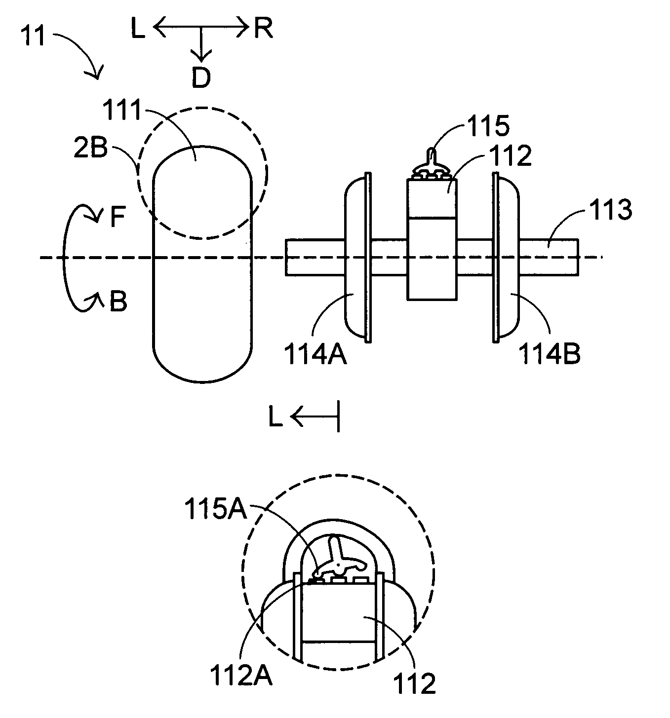
[0005]It is an object of the present invention to provide a pointing device capable of precisely controlling lateral movements of the cursor shown on the display screen without largely increasing overall volume of the pointing device.

Problems solved by technology

As previously described, since the sensing member is typically arranged on bilateral sides or peripheries of the scroll wheel assembly, the overall volume of the pointing device fails to meet the increasing requirement of minimization.
In addition, the approach of laterally stirring the scroll wheel assembly may lead to excessive swing amplitude, and thus the scroll wheel assembly is hard to be precisely controlled.

Method used


Image

  • Pointing device
  • Pointing device
  • Pointing device

Examples


second embodiment

[0024]a pointing device is also communicable to a computer system or an electronic apparatus with a display screen, thereby controlling lateral movement of a cursor or scrolling an image on the display screen in response to a control signal. The scroll wheel assembly 21 used in this embodiment will be illustrated with reference to FIGS. 3A˜3C. As shown in FIG. 3A, the scroll wheel assembly 21 comprises a rotatable member, a soft member 211 and a sensing member 212. The rotatable member includes two rotor disks 214A and 214B disposed on opposite sides of a shaft 213 and made of flexible material. The soft member 211 can be contacted by the user's finger. The sensing member 212 is arranged between the rotatable member and the soft member 211. Once the scroll wheel assembly 21 is fabricated as shown in FIG. 3B, the sensing member 212 and portions of the rotor disks 214A and 214B are covered by the soft member 211.

[0025]FIG. 3B is a cross-sectional view illustrating the scroll wheel ass...

third embodiment

[0027]a pointing device is also communicable to a computer system or an electronic apparatus with a display screen, thereby controlling lateral movement of a cursor or scrolling an image on the display screen in response to a control signal. The scroll wheel assembly 31 used in this embodiment will be illustrated with reference to FIGS. 4A˜4E. As shown in FIG. 4A, the scroll wheel assembly 31 comprises a rotatable member, a soft member 311 and a sensing member 312. The rotatable member includes two rotor disks 314A and 314B disposed on opposite sides of a shaft 313. The soft member 311 can be contacted by the user's finger. The sensing member 312 is arranged between the rotatable member and the soft member 311. Once the scroll wheel assembly 31 is fabricated as shown in FIG. 4B, the sensing member 312 and portions of the rotor disks 314A and 314B are covered by the soft member 311.

[0028]The sensing member 312 includes two pressure sensing elements 312A and 312B facing to and in cont...


PUM


Abstract

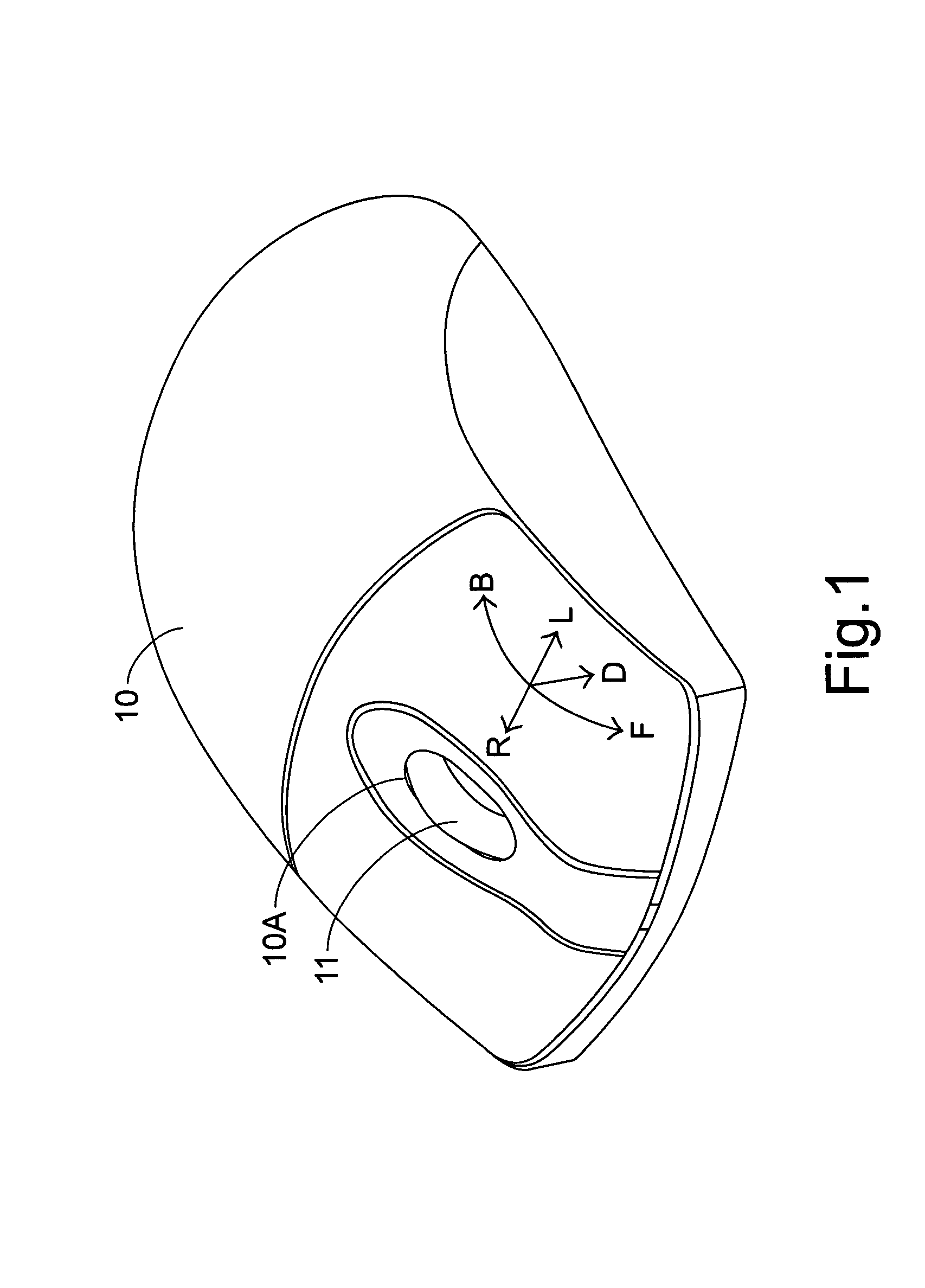
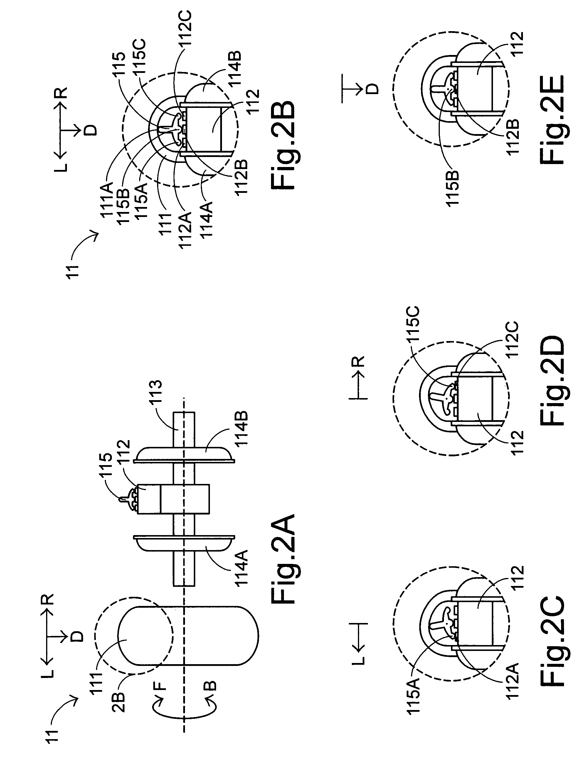
A pointing device is communicated with a computer system for controlling movement of a cursor shown on a display screen of the computer system. The pointing device includes a housing and a scroll wheel assembly. The housing has an opening therein. The scroll wheel assembly is positioned within the opening of the housing and a portion thereof protrudes away from the outer surface of the housing. The scroll wheel assembly includes a rotatable member, a soft member covering the rotatable member, and a sensing member arranged between the rotatable member and the soft member. The sensing member is actuated in response to deformation of the soft member when a lateral force is applied on the soft member, thereby controlling lateral movement of the cursor.

Description

FIELD OF THE INVENTION[0001]The present invention relates to a pointing device, and more particularly to a pointing device for scrolling an image on a display screen, controlling lateral movement of a cursor and generating a setting signal.BACKGROUND OF THE INVENTION[0002]Pointing devices such as mice have been widely employed in computer systems or other electronic apparatuses equipped with a display screen so as to control movement of a cursor on the display screen or scroll an image relative to the display screen. In addition, the pointing device may be actuated to generate responsive setting signals to conduct further data processing operations. As known, a scroll wheel assembly is usually provided on a pointing device and used by the computer operators to scroll an image relative to the display screen. Since the scroll wheel assembly is rotatable in either a forward direction or a backward direction, the image would be scrolled upwards or downwards. For a purpose of controlling...

Claims


Application Information

Patent Timeline
Patent Type & Authority Patents(United States)
IPC IPC(8): G09G5/00G06F3/038
CPCG06F3/03543G06F3/0362G06F3/038
Inventor LIU, SEN-HSIANGHUANG, HUANG-FENGFU, HAI-BING
Owner INTELLECTUAL VENTURES I LLC
Why Eureka
Try Eureka