Mesh editing with gradient field manipulation and user interactive tools for object merging

a gradient field and object merging technology, applied in the field of computer generated graphical images, can solve the problems of difficult to determine the merging curve, difficult to perform the merging operation of objects with dissimilar shapes and sizes,

Inactive Publication Date: 2009-09-15
MICROSOFT TECH LICENSING LLC
View PDF47 Cites 31 Cited by
  • Summary
  • Abstract
  • Description
  • Claims
  • Application Information

AI Technical Summary

Problems solved by technology

In the prior mesh editing systems, it has been challenging to perform merging operations of objects having dissimilar shapes and sizes.
In particular, it is challenging to determine a merging curve based on correspondence of vertices on boundary curves of objects to be merged.

Method used


Image

  • Mesh editing with gradient field manipulation and user interactive tools for object merging
  • Mesh editing with gradient field manipulation and user interactive tools for object merging
  • Mesh editing with gradient field manipulation and user interactive tools for object merging

Examples


Embodiment Construction

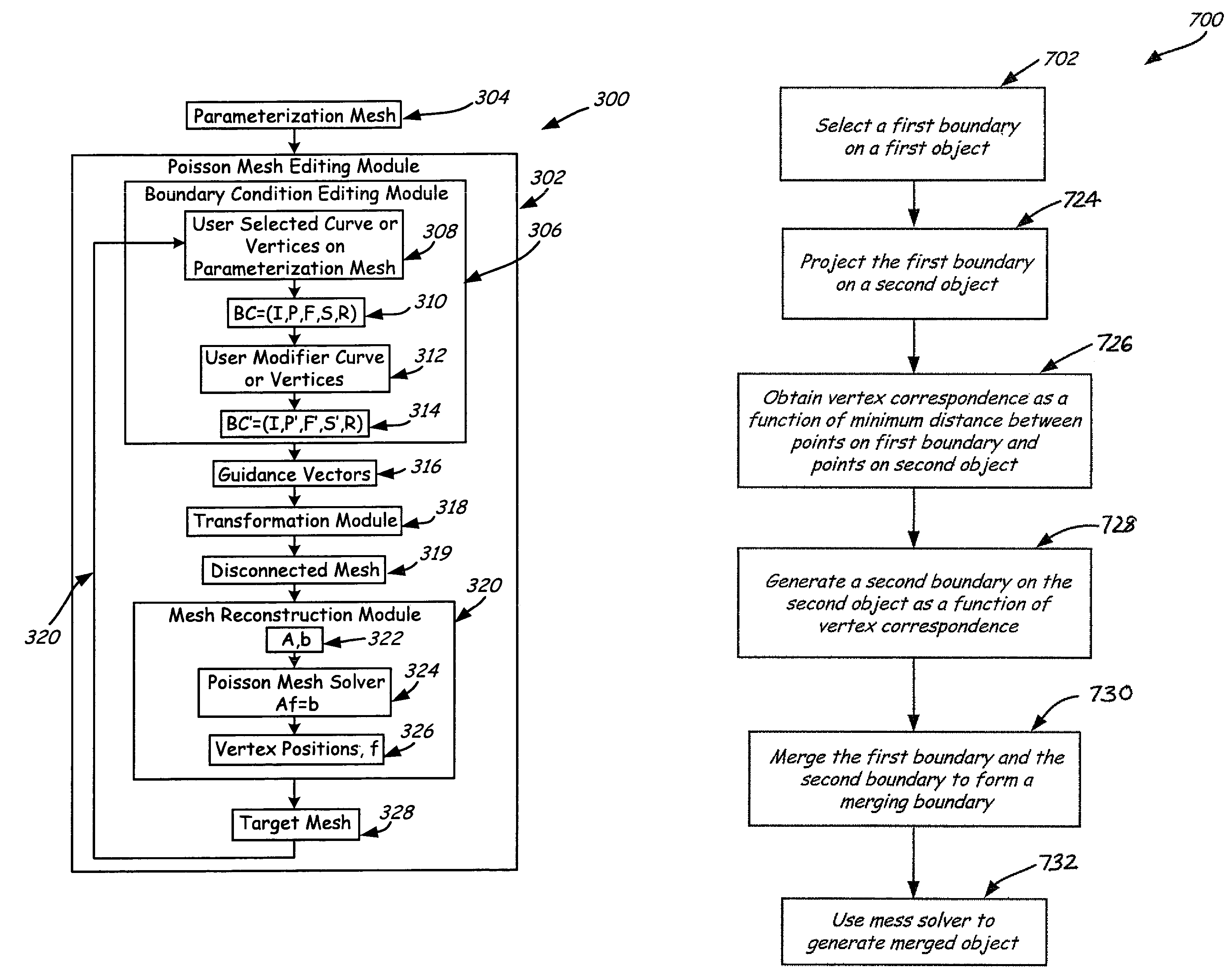
[0031]The present invention relates to a mesh and shape editing system that may or may not use the Poisson equation as its theoretical foundation. In one aspect, methods / modules of merging two object meshes are presented that use various steps or means for determining a boundary or merging curve. Another aspect includes a mesh editing system that uses at least one of these method / modules of determining a boundary curve. However, prior to discussing the present invention in greater detail, an illustrative environment in which the present invention can be used will be discussed first.

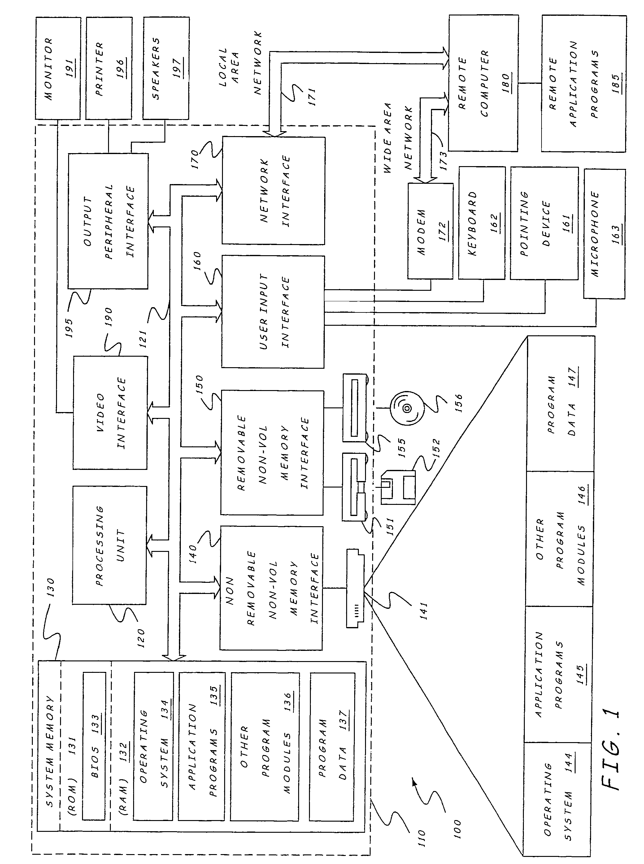
[0032]FIG. 1 illustrates an example of a suitable computing system environment 100 on which the invention may be implemented. The computing system environment 100 is only one example of a suitable computing environment and is not intended to suggest any limitation as to the scope of use or functionality of the invention. Neither should the computing environment 100 be interpreted as having any dependency ...


PUM


Abstract

User interactive methods of determining vertex correspondence between boundaries or curves on objects to be merged is provided. One method relates to projecting a boundary of one object onto a second object to determine a merging curve, along which the two objects will be joined. Another method includes projecting a first object onto a plane to form a planar curve. The planar curve is then mapped to a second object to form a merging curve. Still another method includes interactively selecting corresponding key vertices on different objects to form a merging curve. A system presented that can use one or more of the methods of determining correspondence between boundaries. A merged object can be generated from the merging curve using a mesh solver, such as a Poisson or non-Poisson mesh solver.

Description

BACKGROUND OF THE INVENTION[0001]The present invention relates to computer generated graphical images. More particularly, the present invention relates to mesh editing systems.[0002]Computer graphics are used in computer games, engineering and design, television and cinema, and similar applications where a computer-generated image is desired. Computer graphics can generally be two or three dimensional, but three-dimensional computer graphics, by providing height, width, and depth to an object, are especially useful in realistically modeling and rendering an object.[0003]Commonly, computer graphics systems can comprise free form or scanned models that are stored in a computer as a mesh or lattice of interconnected triangles. Each triangle represents a different flat or planar surface on an object. The mesh can be manipulated or edited during editing operations by moving, rotating, and / or stretching the triangles. Examples of such operations include deformation, both large scale and d...

Claims


Application Information

Patent Timeline
Patent Type & Authority Patents(United States)
IPC IPC(8): G06T17/20G06T15/00G09G5/00G06T17/00
CPCG06T17/205G06T17/20
Inventor ZHOU, KUNGUO, BAININGSHUM, HEUNG-YEUNG
Owner MICROSOFT TECH LICENSING LLC
Why Eureka
Try Eureka