
Camera lens assembly

a technology of lens assembly and lens body, which is applied in the direction of mounting, instruments, optics, etc., can solve the problems of difficult to provide optical zoom function, handshake correction function, auto-focusing function and other problems, and achieve the effect of simple driving unit configuration, convenient mounting and smooth movement of the lens assembly

Active Publication Date: 2009-09-15
SAMSUNG ELECTRONICS CO LTD +1
View PDF3 Cites 21 Cited by
  • Summary
  • Abstract
  • Description
  • Claims
  • Application Information

AI Technical Summary

Benefits of technology

[0010]Accordingly, the present invention has been made in part to solve at least some of the above-mentioned problems known in the prior art. The present invention provides a camera lens assembly which has an auto-focusing function and can be easily miniaturized.
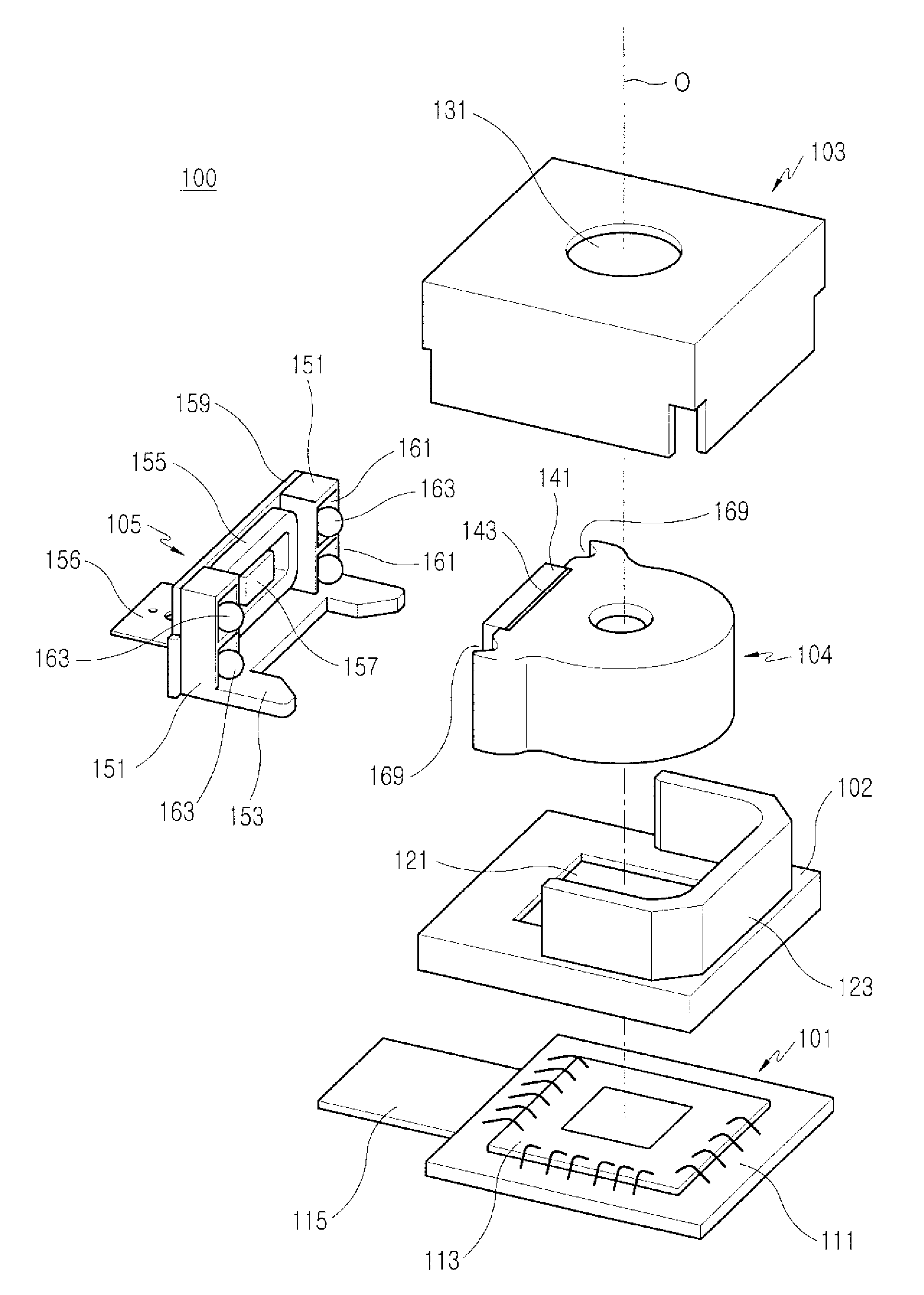
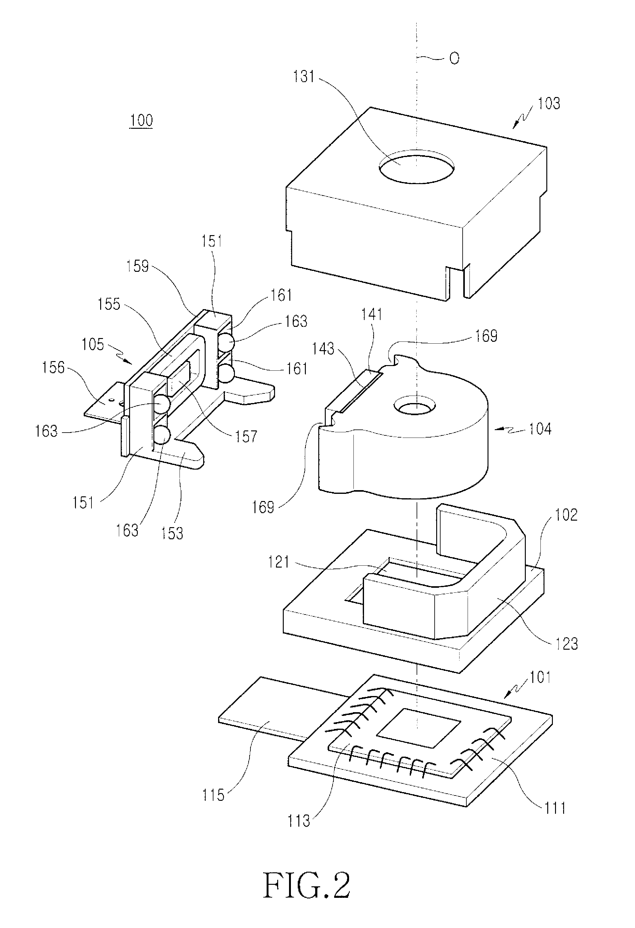
[0013]According to an exemplary embodiment of the present invention, a camera lens assembly includes: a driving unit for moving a lens assembly forward and backward in a direction of an optical axis so as to embody an auto-focusing function, the driving unit being provided in one side of the lens assembly, and a guide section between the lens assembly and the driving unit so as to enable smooth forward / backward movement of the lens assembly. According to a particular exemplary embodiment of the present invention, the configuration of the driving unit includes a voice coil motor, and provides balls, as the guide section, between the lens assembly and the driving unit so as to enable smooth movement of the lens assembly. The guide section as configured above enables smooth forward / backward movement of the lens assembly, and thus the configuration of the driving unit is simplified. Therefore, a camera lens assembly is miniaturized enough to be easily mounted to a portable device such as a mobile communication terminal.

Problems solved by technology

Although, a mobile communication terminal has gradually made inroads into the digital camera market with the improvement in the precision of performance and a manufacturing technique for a camera lens assembly, there are still a number of limitations to raising the performance of a camera mounted to a mobile communication terminal up to the same level as a standalone digital camera, particularly when considering that the main functions of a mobile communication terminal are the securement of a communication function, as well as portability.
However, it is difficult to provide an optical zoom function, an auto-focusing function and a handshake correction function in a camera lens assembly mounted to a mobile communication terminal because the main functions (such as the communication function and portability) must be preferentially considered for the design of a mobile communication terminal.

Method used


Image

  • Camera lens assembly
  • Camera lens assembly
  • Camera lens assembly

Examples


Embodiment Construction

[0019]Hereinafter, exemplary embodiments of the present invention will be described in detail with reference to the accompanying drawings. In the following description of the present invention, a detailed description of known functions and configurations incorporated herein may be omitted when such inclusion would obscure appreciation of the subject matter of the present invention by a person of ordinary skill in the art. A person of ordinary skill in the art understands and appreciates that the claimed invention is not limited to the illustrations and associated descriptions that have been provided herein for explanatory purposes.

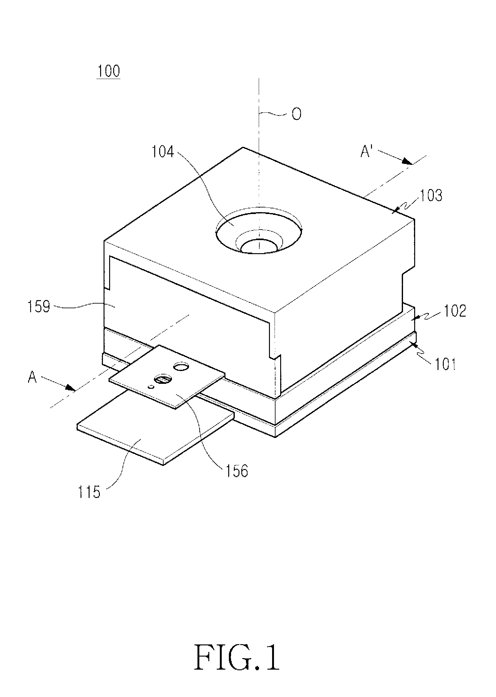
[0020]As shown in FIGS. 1 to 4, a camera lens assembly 100 according to one exemplary embodiment of the present invention includes a driving unit 105 (shown in exploded view in FIG. 2) provided in one side of a lens assembly 104 so as to move the lens assembly 104 forward and backward in the direction of an optical axis 0, and a guide section between the l...


PUM


Abstract

A camera lens assembly providing focal length adjustment to permit mounting in a personal portable terminal. The camera lens assembly includes a lens assembly; a driving unit provided in one side of the lens assembly; and a guide section provided between the lens assembly and the driving unit, wherein the lens assembly moves forward and backward in a direction of an optical axis to the driving unit by guidance of the guide section. The guide section enhances an auto-focusing function and simplifies mounting of the camera lens assembly, rendering it possible to secure portability even when a camera is mounted to a miniaturized personal portable device such as a mobile communication terminal, a portable computer or the like.

Description

CLAIM OF PRIORITY[0001]This application claims priority under 35 U.S.C.§ 119 from an application entitled “Camera Lens Assembly,” filed with the Korean Intellectual Property Office on Apr. 10, 2007 and assigned Serial No. 2007-35155, the contents of which are incorporated herein by reference in its entirety.BACKGROUND OF THE INVENTION[0002]1. Field of the Invention[0003]The present invention relates to an adjustable camera lens assembly. More particularly, the present invention relates to a camera lens assembly configured in such a manner that it can automatically adjust the focal length of a lens in an optical unit mounted to a digital camera, a mobile communication terminal or the like.[0004]2. Description of the Related Art[0005]Recent advances in the field of photography, which include improvements in digital camera manufacturing techniques, have brought about the advent of a micro-sized / light-weighted camera lens assembly, as it is now possible to mount a camera to a mobile com...

Claims


Application Information

Patent Timeline
Patent Type & Authority Patents(United States)
IPC IPC(8): G02B7/02
CPCG02B13/001G02B7/102G02B7/02
Inventor SHIN, DOO-SIKSEOL, JIN-SOOLEE, JONG-PILLEE, BYUNG-CHEOL
Owner SAMSUNG ELECTRONICS CO LTD
Learn More