
Sampled accumulation system and method for jitter attenuation

a jitter attenuation and accumulation system technology, applied in the field of digital envelope frame communications, can solve the problems of loss of data downstream from the sender, clock variations, and aperiodic or non-periodic pointer adjustment may be bursty, and achieve the effect of reducing the number of gates required, reducing the rate of fsample, and high precision valu

Active Publication Date: 2009-09-15
MACOM CONNECTIVITY SOLUTIONS LLC
View PDF13 Cites 0 Cited by
  • Summary
  • Abstract
  • Description
  • Claims
  • Application Information

AI Technical Summary

Benefits of technology

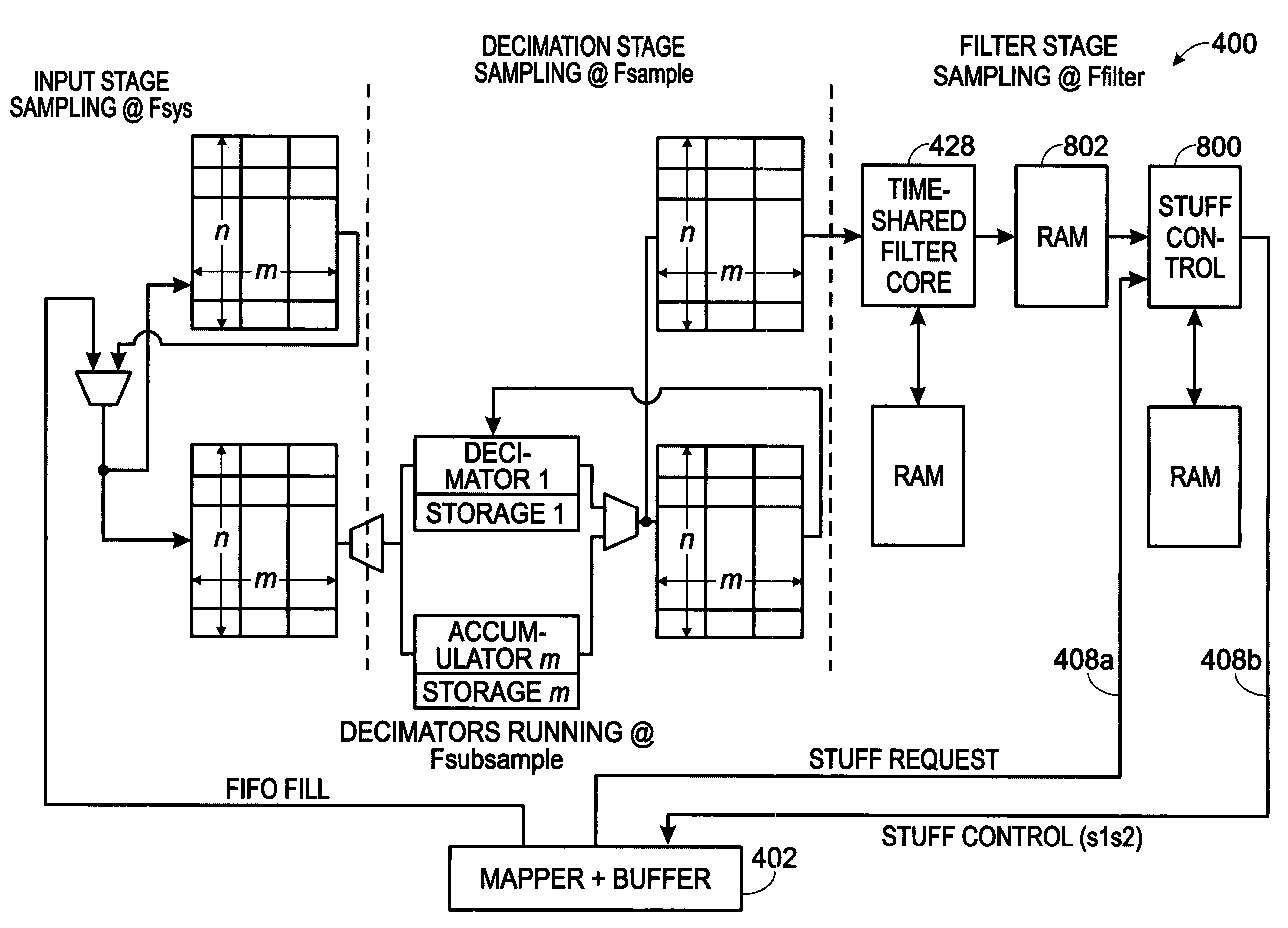
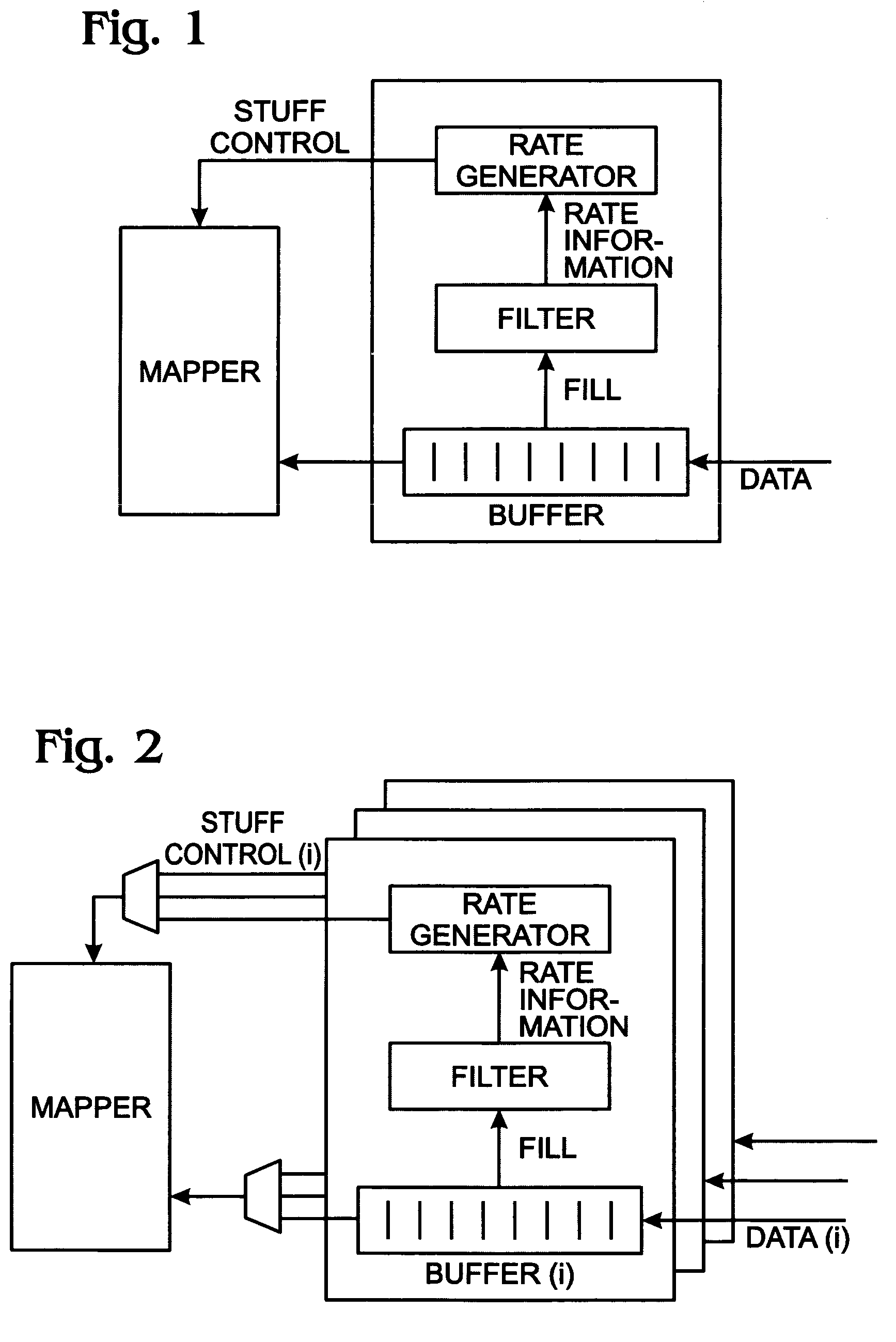
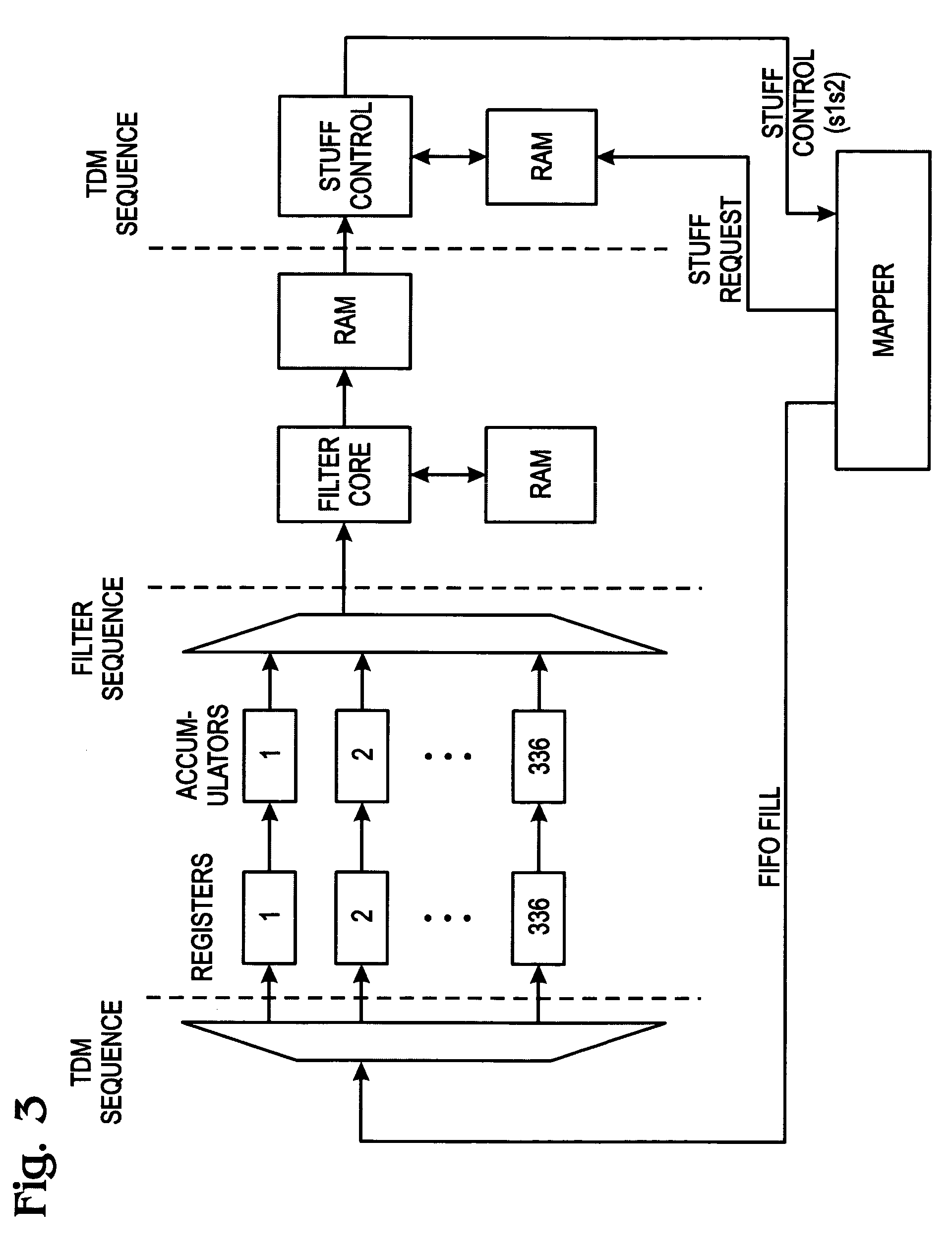
[0029]The present invention is built upon an evaluation of the frequencies in the system, including: the system clock rate; the data rates to be supported (DS1 and E1, or DS3 and E3); and, the characteristics of the various mapping formats supported for each of those data rates (e.g. VT1.5 and M13 for DS1, and VT2.0 and G.747 for E1). The present invention uses an averaging process for each channel (tributary). Buffer-fill information is received for each channel at Fsys, and averaged over a number of Fsys clock cycles, to produce a higher precision value supplied at a reduced rate Fsample. A filter core accepts buffer-fill sampled at the rate Fsample. A stuff rate generator takes the filter output and directly drives the stuff control bits in the mapper. Fsample is chosen so that the system processes all the channels without falling behind the rate at which the mapper requires stuff control inputs, which is once per superframe in the case of VT1.5, for example. The entire system operates such that the rate recovery for each channel is stable and the filtering is adequate to ensure that the mapping is performed in a manner that satisfies transmission standards. By timesharing the filter block, the present invention is able to reduce the number of gates required.

Problems solved by technology

These variations in clock signals between various network elements may cause a loss of data downstream from the sender if the clock signal at which data is written to the synchronous payload and the clock signal at which the data is read from the synchronous payload are sufficiently different.
For example, network clock instability, electrical noise and interference, effective changes in the length of transmission media, changes in the velocity of propagation, Doppler shifts, irregular timing information, and other electrical and network problems may all cause clock variations.
An aperiodic or non-periodic pointer adjustment may be bursty in nature when caused by a transient problem or condition within the network.
Jitter refers to the phase variations in the clock signal, which may cause errors in identifying bit positions and values accurately, and is therefore an issue in synchronous systems.
Each network element adds some amount of noise to the SPE that eventually contributes to the timing instability in the form of jitter and wander in the recovered payload signal.
A PLL is most effective at filtering out high frequency jitter components, i.e., those with a frequency greater than 10 Hz, but is less effective at filtering out the low frequency wander components.
In addition, the large time constants required would result in a PLL that is slow to lock onto the reference signal and would cause long delays in recovering lock after a transient event.
One source of wander errors in the output data rate can be caused by the pointer adjustments within the synchronous signals.
Each pointer adjustment signal or asynchronous gap data results in a data gap for a given number of clock cycles.
The inconsistent nature of the gapped data can result in large changes in the data output rate.
Data overflow occurs when data is written to the elastic store at a faster rate than usual, or read at a slower rate than usual, causing the elastic store to accumulate data.
In these conditions, the elastic store may be unable to store all of the incoming data, and data may be lost.
Similarly, data underflow occurs when data is written to the elastic store at a slower rate than usual, or read at a faster rate than usual, causing the elastic store to lose data.
Similar problems related to the processing of the VT pointer bytes occur, and the positive justification of the VT pointer bytes is accomplished by assigning the bytes immediately after the V3 bytes as positive stuff opportunity bytes.
In addition, the wander and jitter associated with the pointer adjustments is also uncorrelated between the transport overhead pointer bytes and the VT overhead pointer bytes.
The highly non-uniform input data rate to a SONET SPE is primarily due to the presence of transport overhead (TOH) and the position of data bits and stuff bits in the SONET SPE.
Thus, there may be long gaps with no data when TOH data is present.

Method used


Image

  • Sampled accumulation system and method for jitter attenuation
  • Sampled accumulation system and method for jitter attenuation
  • Sampled accumulation system and method for jitter attenuation

Examples


Embodiment Construction

[0042]Various embodiments are now described with reference to the drawings. In the following description, for purposes of explanation, numerous specific details are set forth in order to provide a thorough understanding of one or more aspects. It may be evident, however, that such embodiment(s) may be practiced without these specific details. In other instances, well-known structures and devices are shown in block diagram form in order to facilitate describing these embodiments.

[0043]As used in this application, the terms “component,”“module,”“system,” and the like are intended to refer to a computer-related entity, either hardware, firmware, a combination of hardware and software, software, or software in execution. For example, a component may be, but is not limited to being, a process running on a processor, a processor, an object, an executable, a thread of execution, a program, and / or a computer. By way of illustration, both an application running on a computing device and the ...


PUM


Abstract

A system and method are provided for a sampled accumulation method that maps information into Synchronous Payload Envelopes (SPEs). The method buffers data from a plurality of tributaries, and sequentially stores buffer-fill information for each tributary in a first memory, at a rate of up to one tributary per system clock (Fsys) cycle. A stored accumulation of buffer-fill information for each tributary is updated at a sample rate frequency (Fsample), where Fsample≦Fsys. The stored accumulation of buffer-fill information is used to calculate stuff bit opportunities for each tributary. As a result, the rate of data being mapped into outgoing tributaries is regulated, and the outgoing mapped tributaries are combined in a SPE.

Description

BACKGROUND OF THE INVENTION[0001]1. Field of the Invention[0002]This invention generally relates to digital envelope-framed communications and, more particularly, to a system and method for filtering buffer-fill information that is used in the calculation of stuff bit opportunities for loading data tributaries into a Synchronous Payload Envelope (SPE).[0003]2. Description of the Related Art[0004]In a synchronous communications network, digital payload data is carried at a particular clock frequency within a synchronous message format. This payload data may include both asynchronous digital data and synchronous digital data originating at a different data rate in a foreign digital network. The Synchronous Optical Network (SONET), and its European counterpart the Synchronous Digital Hierarchy (SDH), provide a standard format of transporting digital signals having various data rates, such as a DS-0, DS-1, DS-1C, DS-2, or a DS-3 signal and their European counterparts within a Synchronou...

Claims


Application Information

Patent Timeline
Patent Type & Authority Patents(United States)
IPC IPC(8): H04J3/22
CPCH04J3/1611H04J3/076
Inventor SUBRAHMANYAN, RAVISREENIVAS, VENKAT
Owner MACOM CONNECTIVITY SOLUTIONS LLC
Learn More