Fluent material confinement system

a material confinement and fluid technology, applied in the direction of umbrellas, buttress dams, paper/cardboard articles, etc., can solve the problems of difficult to determine whether complementary slot connectors are securely connected, difficult to stack a plurality of grids to form a wall, and difficult to determine the corr

Inactive Publication Date: 2009-09-22
GEOCELL SYST
View PDF50 Cites 24 Cited by
  • Summary
  • Abstract
  • Description
  • Claims
  • Application Information

AI Technical Summary

Benefits of technology

[0009]A fluent material confinement system configured to receive a granular fluent material to form a temporary barrier structure is disclosed, wherein the fluent material confinement system includes a plurality strips, the plurality of strips including a plurality of lengthwise strips and a plurality of widthwise strips coupled with each other to define a plurality of open cells, wherein the plurality of lengthwise strips includes at least one wider lengthwise strip configured to extend in

Problems solved by technology

For example, the connector slots may be difficult to connect in inclement conditions, as it may be difficult to determine the correct grid orientation in which the connector slots line up with the correct complementary slots.
Likewise, it may be difficult to determine whether complementary slot connectors are securely connected.
Additionally, the ends of the strips of the grids disclosed in the Johnson, Jr. patents may tend to dog-ear when the cells formed at the boundary between adjacent grids are filled with a fluent material due to the connector slots.
This may prevent these cells from being

Method used


Image

  • Fluent material confinement system
  • Fluent material confinement system
  • Fluent material confinement system

Examples


first embodiment

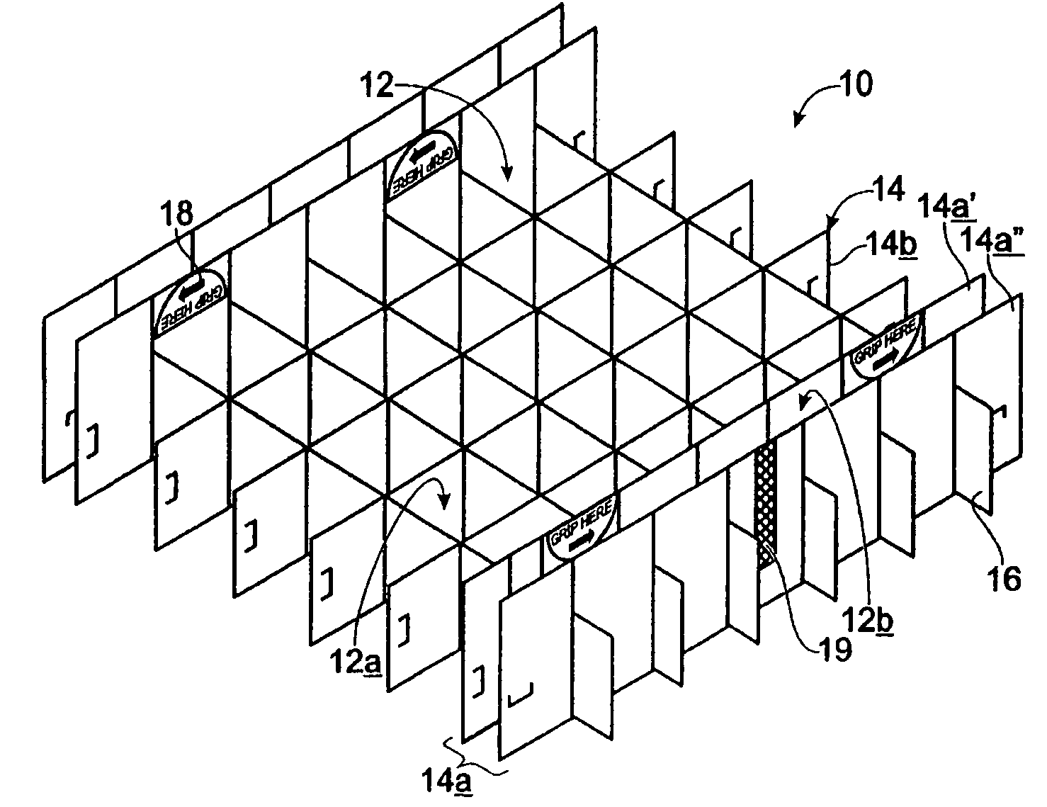
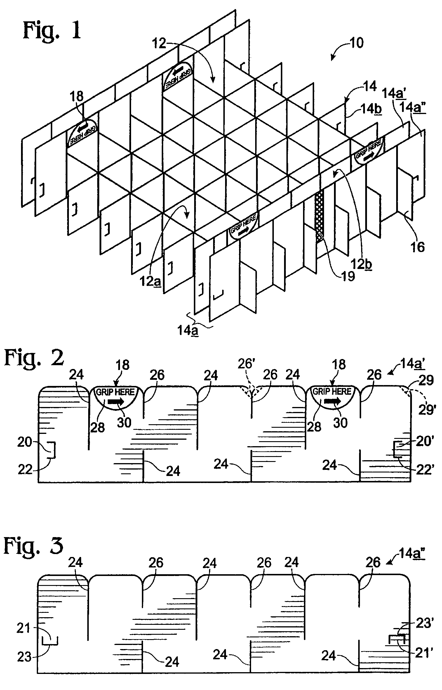
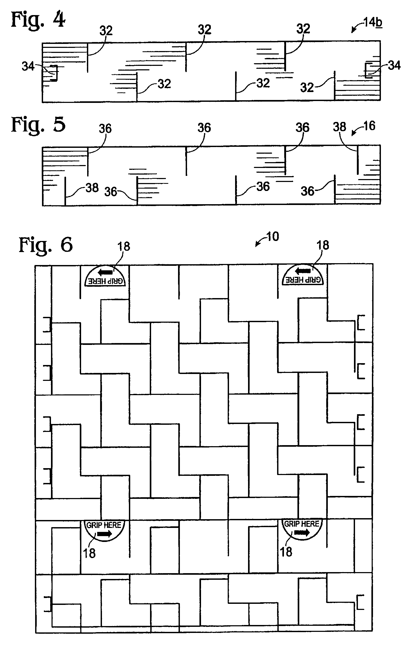
[0042]FIG. 1 shows, generally at 10, a fluent material confinement system. Fluent material confinement system 10 is formed from a plurality of elongate, generally strip-shaped members coupled together in such a manner as to define an array of open-ended cells 12. The plurality of strip-shaped members includes a plurality of lengthwise strips 14, and a plurality of widthwise strips 16. Lengthwise strips 14 may include strips of a first, greater width 14a, and strips of a second, lesser width 14b. Lengthwise strips 14 may also include strips with different types of connectors, as described in more detail below. The depicted arrangement of lengthwise strips 14 and widthwise strips 16 defines at least two different types of cells, interior cells 12a and exterior border cells 12b. Furthermore, the depicted arrangement of strips allows fluent material confinement system 10 to be movable between an open configuration (shown in FIG. 1) and at least one collapsed configuration (described in ...

second embodiment

[0087]FIG. 11 shows, generally at 100, a fluent material confinement system, with different connecting structures than fluent material confinement system 10. Fluent material confinement system 100 has many of the same features as fluent material confinement system 10. For example, fluent material confinement system 100 includes a plurality of interior cells 102a bordered by a plurality of border cells 102b formed from an interconnected network of lengthwise strips 104 and widthwise strips 106. Lengthwise strips 104 may include both wider lengthwise strips 104a and narrower lengthwise strips 104b. Furthermore, fluent material confinement system 100 may include a plurality of deployment indicators 108 configured to assist the deployment of the fluent material confinement system in low visibility conditions. The depicted fluent material confinement system 100 includes two wider lengthwise strips 104a, each positioned in a second-to-outermost position. However, either more or fewer wide...


PUM


Abstract

A fluent material confinement system configured to receive a granular fluent material to form a temporary barrier structure is disclosed, wherein the fluent material confinement system includes a plurality strips, the plurality of strips including a plurality of lengthwise strips and a plurality of widthwise strips coupled with each other to define a plurality of open cells, wherein the plurality of lengthwise strips includes at least one wider lengthwise strip configured to extend into cells of a next-lowest fluent material confinement system when the fluent material confinement system is stacked on the next-lowest fluent material confinement system, and a stacking error indicator associated with the wider lengthwise strip, wherein the stacking error indicator is configured to be effective in low visibility conditions to indicate to a user a location of an error in stacking of the fluent material confinement system on the next-lowest fluent material confinement system.

Description

CROSS-REFERENCE TO RELATED APPLICATIONS[0001]This application is a continuation of U.S. patent application Ser. No. 11 / 187,342, filed Jul. 21, 2005 now abandoned, which is a continuation-in-part of PCT Patent Application Serial No. PCT / US2004 / 043046, filed Dec. 20, 2004, which claims priority from U.S. Provisional Patent Application Ser. No. 60 / 583,309, filed Jun. 25, 2004, and U.S. patent application Ser. No. 10 / 741,801, filed Dec. 18, 2003. The parent application (U.S. patent application Ser. No. 11 / 187,342) is also a continuation-in-part of U.S. patent application Ser. No. 10 / 984,266, filed Nov. 8, 2004, which is a divisional of U.S. Pat. No. 6,817,806, which is a continuation of U.S. patent application Ser. No. 10 / 086,772, filed Feb. 28, 2002 now abandoned, which claims priority from U.S. Provisional Patent Applications Ser. No. 60 / 272,128, filed on Feb. 28, 2001, and Ser. No. 60 / 274,738, filed on Mar. 9, 2001. These applications are incorporated herein by reference in their ent...

Claims


Application Information

Patent Timeline
IPC IPC(8): E02B7/02E04C2/42
CPCE02B3/108
Inventor ARELLANES, ALVIN M.GREINKE, BARNEYSIKORA, JOHNARELLANES, AARON
Owner GEOCELL SYST
Why Eureka
Try Eureka