Surface pattern for golf balls

a golf ball and surface pattern technology, applied in the field of surface patterns for golf balls, can solve the problems of a bluff body, and a large amount of drag on the ball, and achieve the effect of increasing the friction between the skin and the surface of the ball, reducing and improving the friction of the surfa

Inactive Publication Date: 2009-09-29
ACUSHNET CO
View PDF10 Cites 81 Cited by
  • Summary
  • Abstract
  • Description
  • Claims
  • Application Information

AI Technical Summary

Problems solved by technology

A sphere is a bluff body, an inefficient aerodynamic shape.
This pressure differential causes the flow to separate from the outer surface of the ball, resulting in the majority of the drag force on the ball.
However, this reduction of pressure drag increases skin friction, which is due directly to the shear stress on the ball.

Method used


Image

  • Surface pattern for golf balls
  • Surface pattern for golf balls
  • Surface pattern for golf balls

Examples


example 1

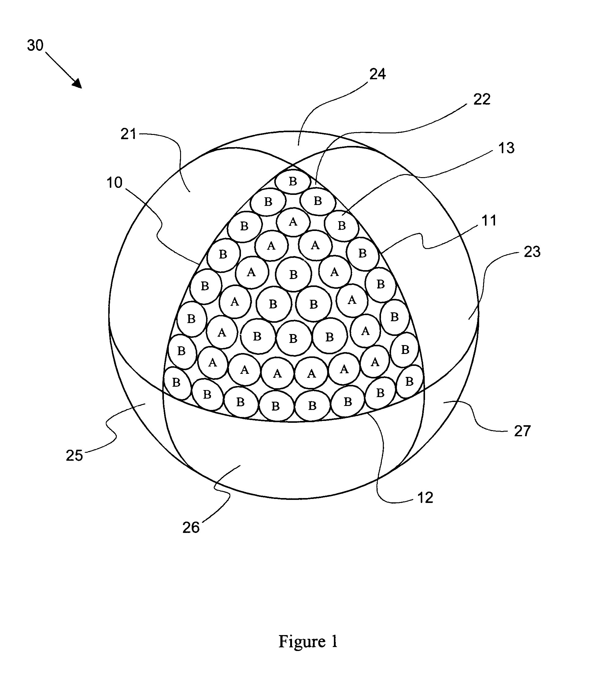
[0049]In a first exemplary embodiment, select dimples of a known dimple pattern are replaced with protrusions. One such known method of packing dimples on a golf ball divides the surface of the golf ball into eight spherical triangles corresponding to the faces of an octahedron, which is a solid bounded by eight triangular plane faces. Dimples are then positioned within each of the surface divisions according to a placement scheme. Alternatively, the surface divisions may be further divided and the resulting subdivisions packed with dimples. Octahedron-based dimple patterns generally cover approximately 60-75% of the golf ball surface with dimples. U.S. Pat. Nos. 5,415,410 and 5,957,786 disclose octahedron-based dimple patterns.

[0050]FIG. 1 shows the surface of a golf ball 30 divided into eight identical spherical triangular regions 21, 22, 23, 24, 25, 26, 27, and 28 (not visible) that correspond to the faces of a regular octahedron. The boundaries of these regions comprise three mu...

example 2

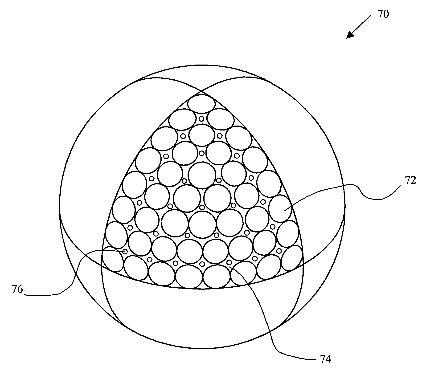
[0063]FIG. 5 illustrates a second embodiment of a golf ball 70 of the present invention. Golf ball 70 has a plurality of dimples 72 arranged thereon according to a known placement scheme. While an octahedron-based dimple pattern is shown as the illustrative embodiment, any dimple pattern may be used.

[0064]When dimples are formed in a golf ball cover, there are necessarily areas of the cover that are not covered by a dimple. These areas are called land area or lands. These unaltered or undimpled areas are spread over the surface of the golf ball. The percentage of the ball surface that the lands comprise is dependent upon the ball's dimple pattern. The surface coverage of dimples is preferably greater than approximately 75%, with the remainder of the surface comprising land areas. The surface coverage is more preferably greater than approximately 80%, and most preferably greater than approximately 85%. The land area works with the turbulence generators to create a turbulent flow of a...

example 3

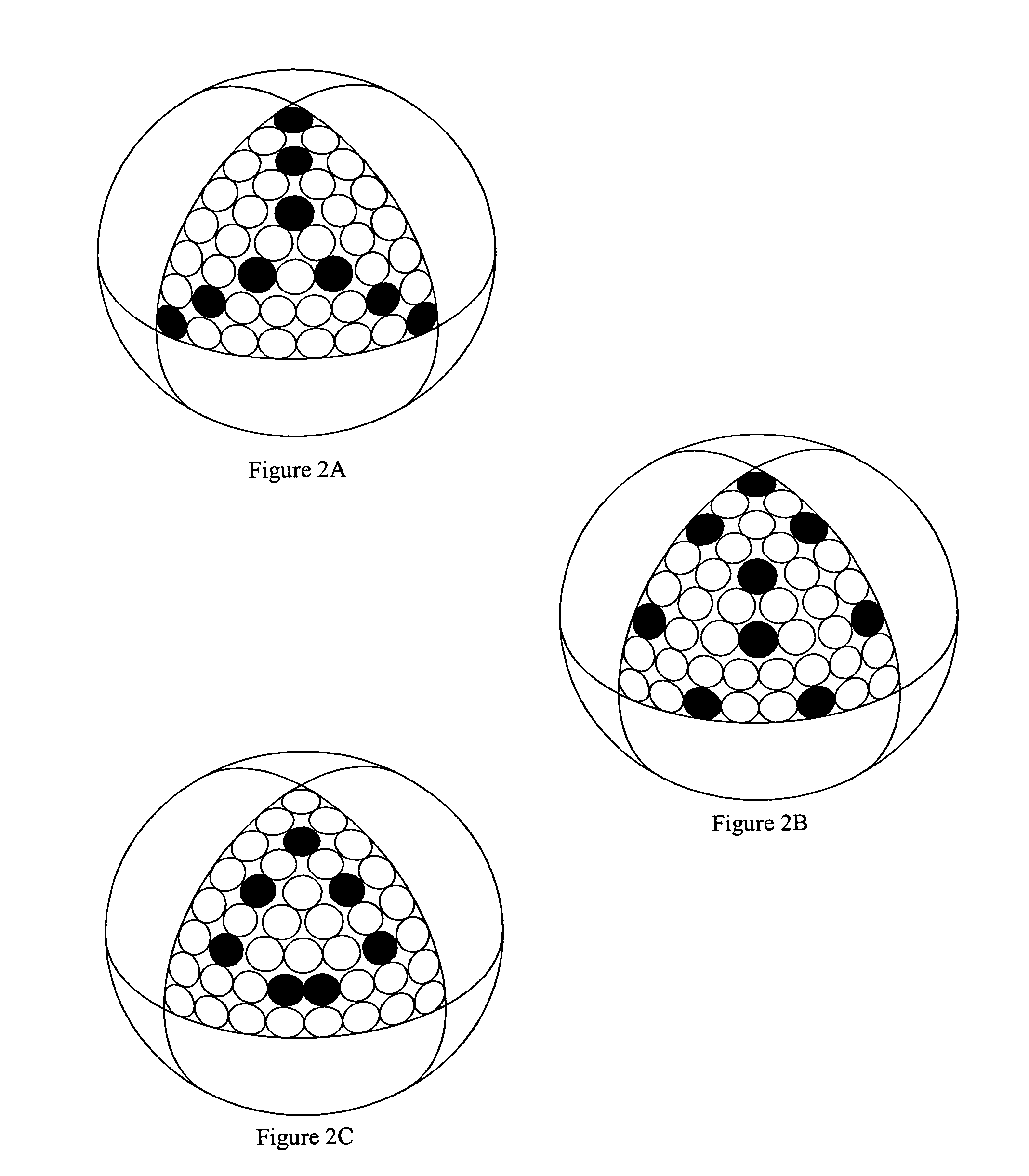
[0067]In a third exemplary embodiment of the present invention, a protrusion pattern is selected and dimples are positioned around the protrusions. The dimples are preferably positioned on unaltered land areas among and between the protrusions. This embodiment is also illustrated in FIG. 5, but with reference 72 identifying protrusions and reference 76 identifying dimples.

[0068]In this embodiment, protrusions are arranged on the surface of a golf ball according to a known pattern. Patterns traditionally used to place dimples on a golf ball, such as the octahedron and icosahedron patterns discussed above, may be used. The dimple locations can be selected by manual placement or with a distribution method. The protrusions and the dimples are distributed about the surface of the golf ball such that the golf ball will exhibit substantially symmetric flight characteristics regardless of where the golf club (or other device) strikes the ball. Like the embodiment of example 2, placement of ...


PUM


Abstract

A golf ball surface pattern including depressions and protrusions is disclosed and claimed. In one embodiment, the depressions and protrusions are positioned on the ball according to a known dimple pattern, with some of the dimples being replaced with protrusions. In another embodiment, the depressions are positioned on the ball according to a known dimple pattern, and protrusions are positioned on the land areas. Alternatively, protrusions can be positioned on the ball according to a known dimple pattern, and depressions positioned on the land areas. The turbulence generators (dimples and protrusions) that are positioned on the land areas can be positioned manually or with a distribution scheme. In another embodiment, the turbulence generators are positioned according to a scheme based on the principles of electromagnetic theory.

Description

BACKGROUND OF THE INVENTION[0001]1. Field of the Invention[0002]The present invention relates generally to surface patterns for round objects. In particular, the present invention relates to surface patterns for golf balls, the surface patterns including both depressions and protrusions.[0003]2. Description of the Related Art[0004]Soon after the introduction of the smooth surfaced gutta percha golf ball in the mid nineteenth century, players observed that the balls traveled further as they got older and more gouged up. The players then began to roughen the surface of new golf balls with a hammer to increase flight distance. The bramble ball, which was introduced around the turn of the 20th century, was formed with bumps on the surface of the ball. Eventually, manufacturers began to manufacture golf balls having dimples formed in the outer surface.[0005]The dimples on a golf ball are important in reducing the aerodynamic forces generated by a ball in flight as a result of the ball's ...

Claims


Application Information

Patent Timeline
Patent Type & Authority Patents(United States)
IPC IPC(8): A63B37/14A63B37/00
CPCA63B37/0004A63B37/0005A63B37/0006A63B37/0009A63B37/002A63B37/0026A63B37/008A63B37/0083A63B37/0089A63B37/009A63B37/0021
Inventor NARDACCI, NICHOLAS M.
Owner ACUSHNET CO
Why Eureka
Try Eureka