Device with chemical surface patterns

a surface pattern and chemical technology, applied in the field of devices with chemical surface patterns, can solve the problems of difficult to achieve the effects of preventing healing reactions, prolonging inflammation, and improving the situation

Inactive Publication Date: 2005-01-20
ETH ZZURICH
View PDF0 Cites 48 Cited by
  • Summary
  • Abstract
  • Description
  • Claims
  • Application Information

AI Technical Summary

Benefits of technology

Another application for chemically patterned surfaces is related to the cell type that is relevant in almost all in vivo implant applications, the macrophage. While macrophages fulfill an important function in “cleaning up” implantation sites and implant surfaces during the healing phase, their extended actions, in particular the occurrence of frustrated phagocytosis and formation from macrophages of multinuclear giant cells (“foreign body giant cells”, FBGC), may lead to sustained inflammation and retarded or prevented healing reactions. Chemically patterned surfaces could improve the situation in at least two different ways: a) if the surface of an implant is patterned into cell-adhesive and non-adhesive areas in dimensions significantly smaller than the size of an attached macrophage, the latter is expected to be prevented from developing a tight seal between the cell membrane and the surface. As a consequence, the macrophage (and osteoclast)—typical excluded volume cannot form, which is a prerequisite for the sustained action of generated, destructive acids, superoxides and peroxides within this excluded electrolyte volume. Therefore, an unfavorably massive degree of chemical attack of biomaterials through macrophage activity could be prevented by usin

Problems solved by technology

In the biomaterial and biosensor area, however, there is a requirement to structure surfaces based on rather delicate, often labile molecules such as proteins, antibodies or nucleic acids (DNA or RNA).
The harsh conditions of the lithographic fabrication steps are likely to be incompatible with these types of biochemical or biological structures.
Type B: While these techniques allow the spatially-controlled transfer of highly sensitive molecules such as proteins, they always involve a local contact of the surface with the stamping material, which may lead to the transfer of unwanted stamp material and thus local contamination that may interfere

Method used


Image

  • Device with chemical surface patterns
  • Device with chemical surface patterns
  • Device with chemical surface patterns

Examples


example 1

SMAP Based on Alkane Phosphate / / Poly(L-lysine)-g-poly(ethylene oxide) System (“Selective Chemical Reactivity Contrast”)

Out of aqueous solutions, dodecyl phosphate (DDP) self-assembles on metal oxides but not on silicon oxide. Subsequent application of PLL-g-PEG renders silicon oxide protein resistant, hence creating a pattern of protein-adhesive and resistant areas. Protein adsorption to the DDP-modified metal oxide surface is in this case non-specific and due to hydrophobic interactions between the hydrophobic alkane phosphate SAM and hydrophobic moieties of the protein.

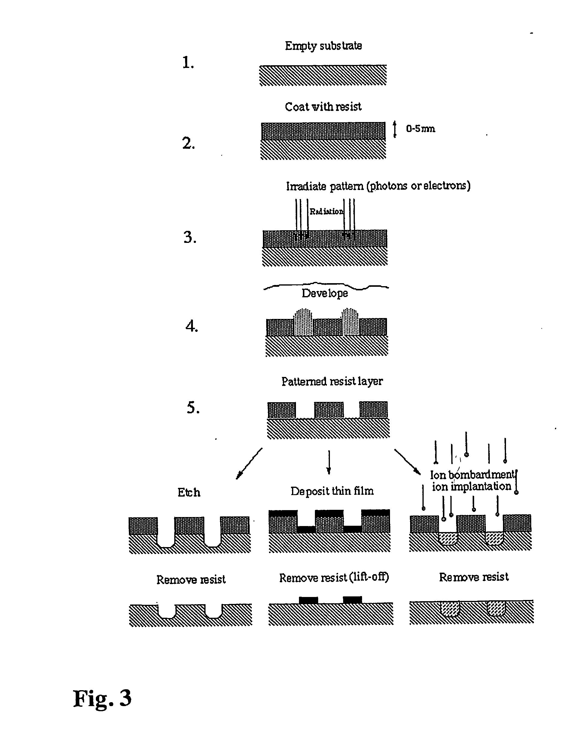
As a specific example, the following consecutive steps were applied: a) The starting surface is produced using photolithography according to general scheme in FIG. 3. A silicon wafer was first coated with 100 nm TiO2 followed by 10 nm SiO2 using the magnetron sputtering technique. After application of a photoresist coating, irradiation through a corresponding mask, dry etching through the SiO2 layer using CF4 / C...

example 2

SMAP Based on Poly(L-lysine)-g-poly(ethylene glycol) / / Poly(L-lysine)-g-poly(ethylene oxide-biotin) System (“Electrostatic Contrast”)

The difference in the isoelectric point between titanium oxide and silicon oxide can be exploited to produce SMAP type II patterns based on electrostatic contrast. This type of SMAP is illustrated using the spontaneous assembly of poly(L-lysine)-g-poly(ethylene glycol) at charged surfaces, which is governed by electrostatic interactions. This technique requires a starting surface with a pattern formed by two materials whose isoelectric points (IEP) are sufficiently different (IEP of SiO2: ca. 2.5; IEP of TiO2: ca. 6). FIG. 9 shows the dependence of the adsorbed mass of PLL-g-PEG(-biotin) (MW of PLL: 20,000 Da, g=3.5, MW of PEG: 2,000 Da) to SiO2 and TiO2 surfaces respectively, as a function of the pH of the PLL-g-PEG aqueous solution to which the surfaces were exposed for a time of 15 min. It is obvious from FIG. 9 that at pH=1.2, PLL-g-PEG (or functi...

example 3

relies on another type of contrast, namely the exploitation of the hydrophobic / hydrophilic contrast already described in Example 1. In a further step, the hydrophobic areas are made protein- and cell-resistant (“non-interactive”) via the interaction with a triblock molecule that contains both a hydrophobic block (to interact with the hydrophobic area of the pattern) and hydrophilic PEG blocks to render the adlayer protein-resistant. The other area of the pattern, the PLL-g-PEG / PEG-X, is cell-interactive due to X=specific peptides interacting with cell membrane receptors.

Protocol: (a) MeO-DDP patches can be modified with PEG-based copolymers possessing a hydrophobic backbone (PPO-PEG). This renders metal oxide-DDP areas protein resistant. PLL-g-PEG / PEG-X (where X stands for a specific receptor functionality, such as biotin or RGD peptide) is used in the subsequent step to render silicon oxide able to bind desired macromolecules, specifically and with high affinity. (b) The pattern...


PUM

PropertyMeasurementUnit
Thicknessaaaaaaaaaa
Thicknessaaaaaaaaaa
Thicknessaaaaaaaaaa

Abstract

A device with chemical surface patterns (defined surface areas of at least two different chemical compositions) with biochemical or biological relevance on substrates with prefabricated patterns of at least two different types of regions (α, β, . . . ), whereas at least two different, consecutively applied molecular self-assembly systems (A, B, . . . ) are used in a way that at least one of the applied assembly systems (A or B or . . . ) is specific to one type of the prefabricated patterns (α or β or . . . ).

Description

BACKGROUND OF THE INVENTION The invention relates to a device with chemical surface patterns, a bioanalytical sensing platform comprising the device, a method for the simultaneous determination of analytes and a biomedical device. Chemical patterning of surfaces i.e., the generation of structures of different chemical composition on surfaces, either in a regular, geometric array or with a statistical distribution of features, is an important technique in a variety of application including microfabrication, microelectronics, micromechanics, biomaterials and biosensors [Kane, R. S., Takayama, S., Ostuni, E., Ingber, D. E., Whitesides, G. M., Patterning proteins and cells using soft lithography, Biomaterials 20 (1999) 2363-2376. Xia, Y., Rogers, J. A., Paul, K. E., Whitesides, G. M., Unconventional Methods for Fabricating and Patterning Nanostructures. Chem. Rev. 99 (1999), 1823-1848]. FIG. 1 shows examples of chemical patterns, which may or may not be connected with topographical va...

Claims


Application Information

Patent Timeline
IPC IPC(8): A61L27/34A61L29/08A61L31/10G01N33/543
CPCA61L27/34A61L29/085A61L31/10B82Y15/00B82Y30/00G01N33/54353G01N33/54366G01N33/54373C08L71/02
Inventor TEXTOR, MARCUSMICHEL, ROGERVOROS, JANOSHUBBELL, JEFFREY A.LUSSI, JOST
Owner ETH ZZURICH
Why Eureka
Try Eureka