Control of the spatial distribution and sorting of micro-or nano-meter or molecular scale objects on patterned surfaces

a technology patterned surfaces, which is applied in the field of control of the spatial distribution and sorting of micro-or nanometer or molecular scale objects on patterned surfaces, can solve the problems of difficult direct control of the spatial distribution and array of micro- or nanometer scale objects across large areas, and achieve the effect of easy sorting of objects by size and broad application in a range of technologies

Inactive Publication Date: 2005-06-02
THE JOHN HOPKINS UNIV SCHOOL OF MEDICINE
View PDF6 Cites 47 Cited by
  • Summary
  • Abstract
  • Description
  • Claims
  • Application Information

AI Technical Summary

Benefits of technology

[0018] Methods of the present invention can deposit and sort objects onto a surface in any geometry that can be created by surface patterning, thus providing broad applicability in a range of technologies. For example, in some embodiments, the objects are deposited and sorted into square rings and / or lines. In one exemplary embodiment, objects are 800 nm particles periodically deposited onto the surface in the form of high-resolution two-dimensional arrays with 1-7 particles per domain.
[0019] Methods of the present invention are further capable of depositing and sorting a mixture of different sized objects. Still further, the pattern or lyophilic region(s) on the surface can comprise patterns or regions of one or more sizes. In general, the objects are only capable of being deposited on regions or patterns that are larger than those objects and, thus, sorting of object deposition by size is easily accomplished.

Problems solved by technology

However, direct control of the spatial distribution and arrays of micro- or nano-meter scale objects across large areas is very difficult.
However, two challenges in nanotechnology are the creation of particle arrays of two or more (homogeneous or heterogenous) objects within a matrix and sorting of (homogeneous or heterogenous) objects.

Method used


Image

  • Control of the spatial distribution and sorting of micro-or nano-meter or molecular scale objects on patterned surfaces
  • Control of the spatial distribution and sorting of micro-or nano-meter or molecular scale objects on patterned surfaces
  • Control of the spatial distribution and sorting of micro-or nano-meter or molecular scale objects on patterned surfaces

Examples


example 1

Materials:

[0076] PDMS stamp with a pattern (e.g. stripes or square grids), 1 mM solution of octadecanethiol (ODT) and 16-mercaptohexadecanoic acid (MHA) in ethanol, gold coated surface, polystyrene latex, Au nanoparticle solution (0.001% in water with a diameter of 20 nm), Nanowires, distilled water, ethanol.

Procedure:

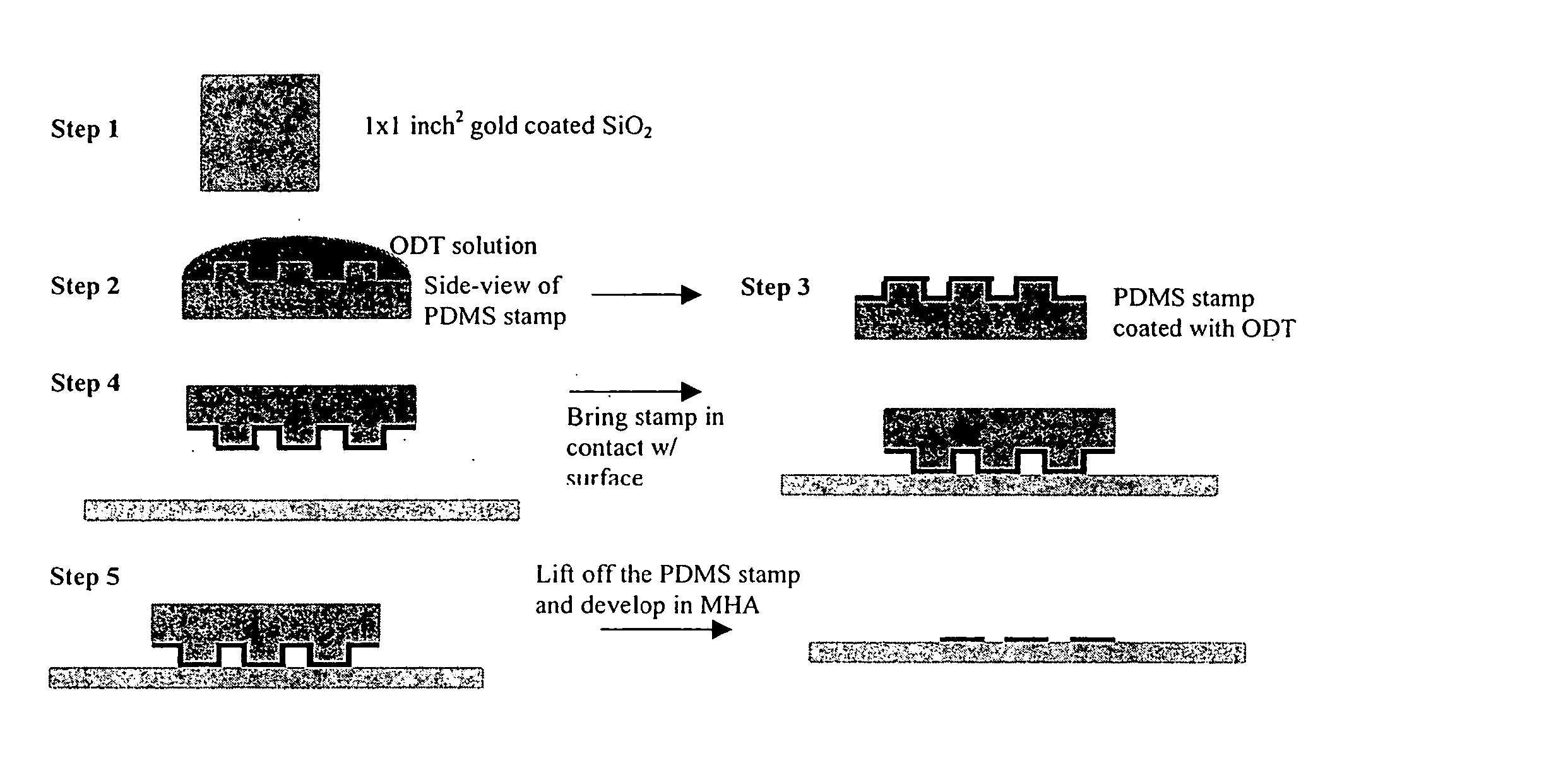
[0077] The first step is to transfer the surfactant molecules in a pattern onto the gold surface. A schematic of this procedure is shown in FIG. 1: [0078] 1. A gold surface was obtained (e.g. 100 nm gold film coated on sublayer of chromium on a SiO2 wafer) and cut a 1 inch square portion. The surface was rinsed with ethanol and blow dried with pure nitrogen gas. [0079] 2. A PDMS stamp was obtained having the desired pattern. FIG. 6 shows a schematic illustration of the PDMS stamp used in this set of experiments. [0080] 3. The PDMS stamp was positioned with the patterned features facing upwards. The patterned face of the stamp was coated with sufficient ODT solutio...

example 2

Materials:

[0094] Substrates or thin films with patterned lyophilic surfaces formed by photolithography, soft lithography or other method, polystyrene latex, Au nanoparticle solution (0.001% in water with a diameter of 20 nm), Nanowires, Lamda DNA, Protein, polymer, distilled water.

Procedure:

[0095] The first step was to form lyophilic patterns on substrates such as silicon wafer, metal and polymer films by photolithography, e-beam lithography and soft lithography. Such methods are discussed herein, e.g. in Example 2, and can be in accordance with known methods.

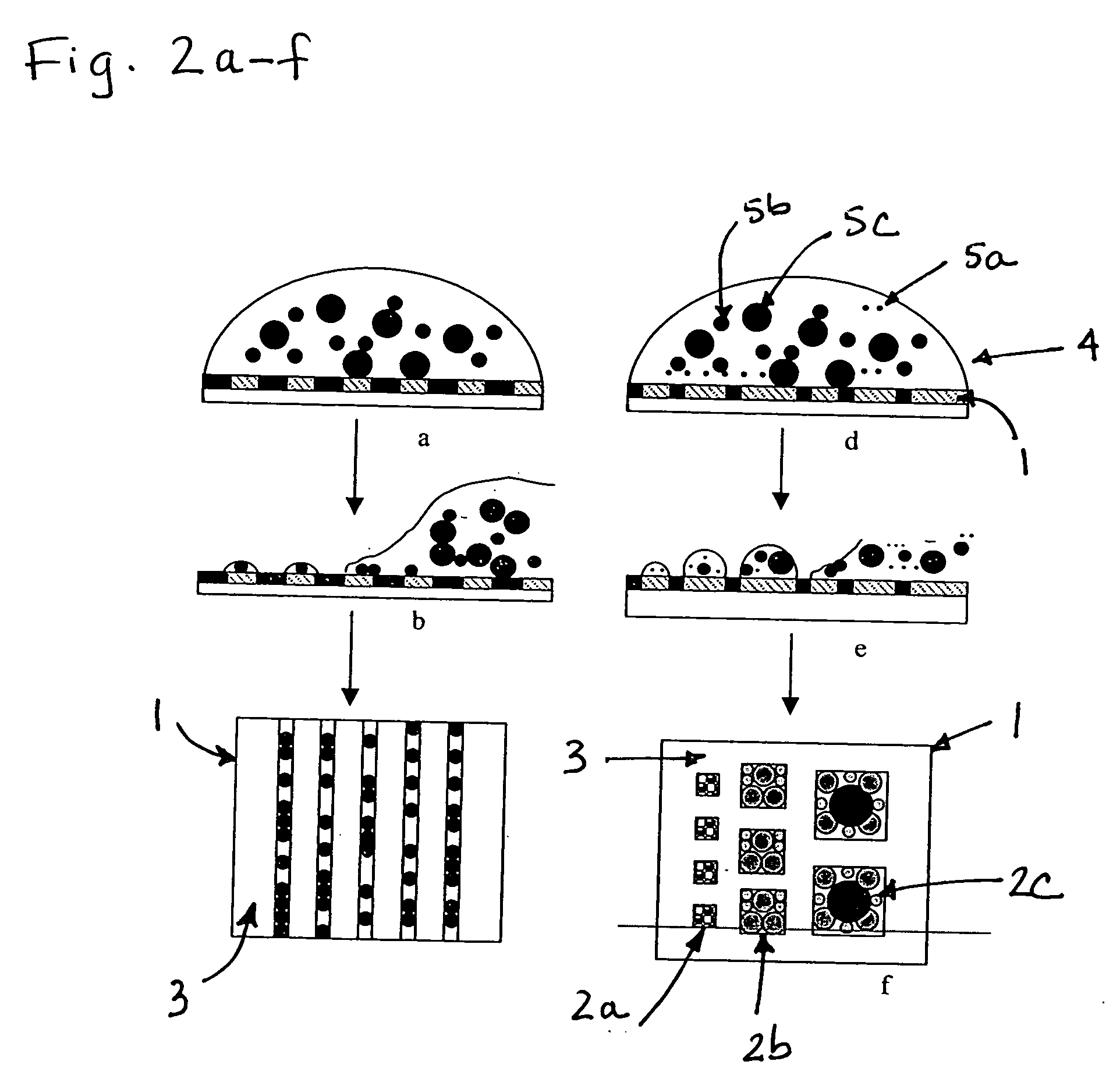
[0096] The next step was to deposit the objects of interest (e.g. colloidal particles) onto the surfaces with lyophilic patterns by drop evaporating and dip coating. Drop evaporating was accomplished as follows: [0097] 1. The substrate was put into a chamber and the temperature and humidity was adjusted as required. [0098] 2. The deposited drop volume fraction of objects in solvents ranged from 10% to 0.00001%. All evapor...

example 3

[0110] A sample was prepared by evaporating a drop of 0.01 wt % mixed suspension on surfaces with 1 μm lyophilic strips and 1 μm lyophobic strip apart at 25° C. and 26% humidity. The particles in suspension comprise a mixture of particles with diameters of 800 nm and 200 nm.

[0111]FIG. 3 shows optical microscopy images of shapes formed by the mixed particles with diameters of 800 nm and 200 nm, and magnification of some regions. The excellent selectivity of the particle deposition can be seen in the magnified images. As shown, all 800 nm particles go to the edge and accumulate locally after depinning and fast evaporation (FIG. 3c, d). The 200 nm particles deposit on lyophilic regions and mimic the parent pattern (FIG. 3b).

[0112] Consider a cylinder cap of radius R with a pinned contact line, created by a fluid wedge with contact angle θ. The height of the spherical cap h is determined simply by: tanθ / 2=h / R. Here, the receding contact angle of surface with 1 μm strip is measured to ...


PUM

PropertyMeasurementUnit
contact anglesaaaaaaaaaa
diameteraaaaaaaaaa
diameteraaaaaaaaaa

Abstract

A method of depositing and sorting micro-scale, nano-scale and molecular-scale objects onto a surface. In particular, the methods can be used to produce arrays of micro- and nanoscale objects on a surface by use of fluidic alignment with surface patterning techniques. In a preferred embodiment of the invention, the objects are sorted and / or spatially distributed and arrayed into micro- or nanometer scale geometries with periodicity on a larger area by evaporation (or other means of selective removal of solvent) of liquid containing molecular scale solutes, nanowires, metallic particles, polymeric particles, inorganic particles or composite particles formed from such materials or preferably, such particles may be sorted and deposited from suspensions by continuously creating and evaporating films of the suspension on patterned substrates.

Description

[0001] The present application claims the benefit of U.S. provisional application No. 60 / 467,460 filed on May 2, 2003, incorporated herein by reference in its entirety.FIELD OF THE INVENTION [0002] This invention relates to a method for depositing and / or sorting objects of interest onto a surface. In particular, the present methods are directed towards depositing microscale, nanoscale and molecular scale objects on a surface and products thereof. Such objects are deposited by means of placing a solvent containing the objects suspended therein on a patterned surface followed by selective removal of the suspending solvent (e.g. by fluid evaporation). In particular, the objects are sorted and deposited by means of creating lyophilic regions of differing dimensions on the surface. Objects of micoscale, nanoscale or molecular scale (in the order of angstroms) can be sorted by size and / or distributed by this method. Methods of the invention are particularly useful in fabrication of a wide...

Claims


Application Information

Patent Timeline
Patent Type & Authority Applications(United States)
IPC IPC(8): B05D1/32B41M3/00G03F7/00
CPCB41M3/006B82Y10/00G03F7/0002B82Y40/00B82Y30/00
Inventor STEBE, KATHLEEN JOANFAN, FENGQUITRUSKETT, VAN NGUYEN
Owner THE JOHN HOPKINS UNIV SCHOOL OF MEDICINE
Why Eureka
Try Eureka