Antireflective member, optical element, display device, method of making stamper and method of making antireflective member using the stamper

A manufacturing method and anti-reflection technology, applied in optical components, optics, instruments, etc., can solve problems such as difficult to copy concave-convex patterns, lack of anti-reflection effect, and reduced visibility

Active Publication Date: 2007-12-12
SHARP KK
View PDF6 Cites 51 Cited by
  • Summary
  • Abstract
  • Description
  • Claims
  • Application Information

AI Technical Summary

Problems solved by technology

[0026] First, according to the conventional concave-convex pattern, since the diffracted light mainly composed of short-wavelength light is generated at a specific angle depending on the incident angle, there is a problem that the visibility is reduced
In particular, when an antireflection material formed with a fine uneven pattern is used for a display device, bluish diffracted light and the like are generated, and visibility is reduced.
[0027] Second, there is a problem that the anti-reflection effect on regular reflection, that is, zero-order reflected diffracted light is not sufficient.
However, it is very difficult to make a metal mold for forming unevenness with a large aspect ratio
In addition, even if such a metal mold can be produced, it is difficult to reproduce the concave-convex pattern with high precision
As a result, if the anti-reflection material is made by the replication method, the desired anti-reflection effect may not be obtained.
[0028] In addition, since the manufacturing method of the above-mentioned (1) to (3) stamper disclosed in Patent Document 6 uses a dry process, expensive equipment is necessary, and it is limited by the size of the equipment, so it is difficult to produce a large-area stamper. Dies with special shapes such as dies or rolls

Method used


Image

  • Antireflective member, optical element, display device, method of making stamper and method of making antireflective member using the stamper
  • Antireflective member, optical element, display device, method of making stamper and method of making antireflective member using the stamper
  • Antireflective member, optical element, display device, method of making stamper and method of making antireflective member using the stamper

Examples


Embodiment approach 1

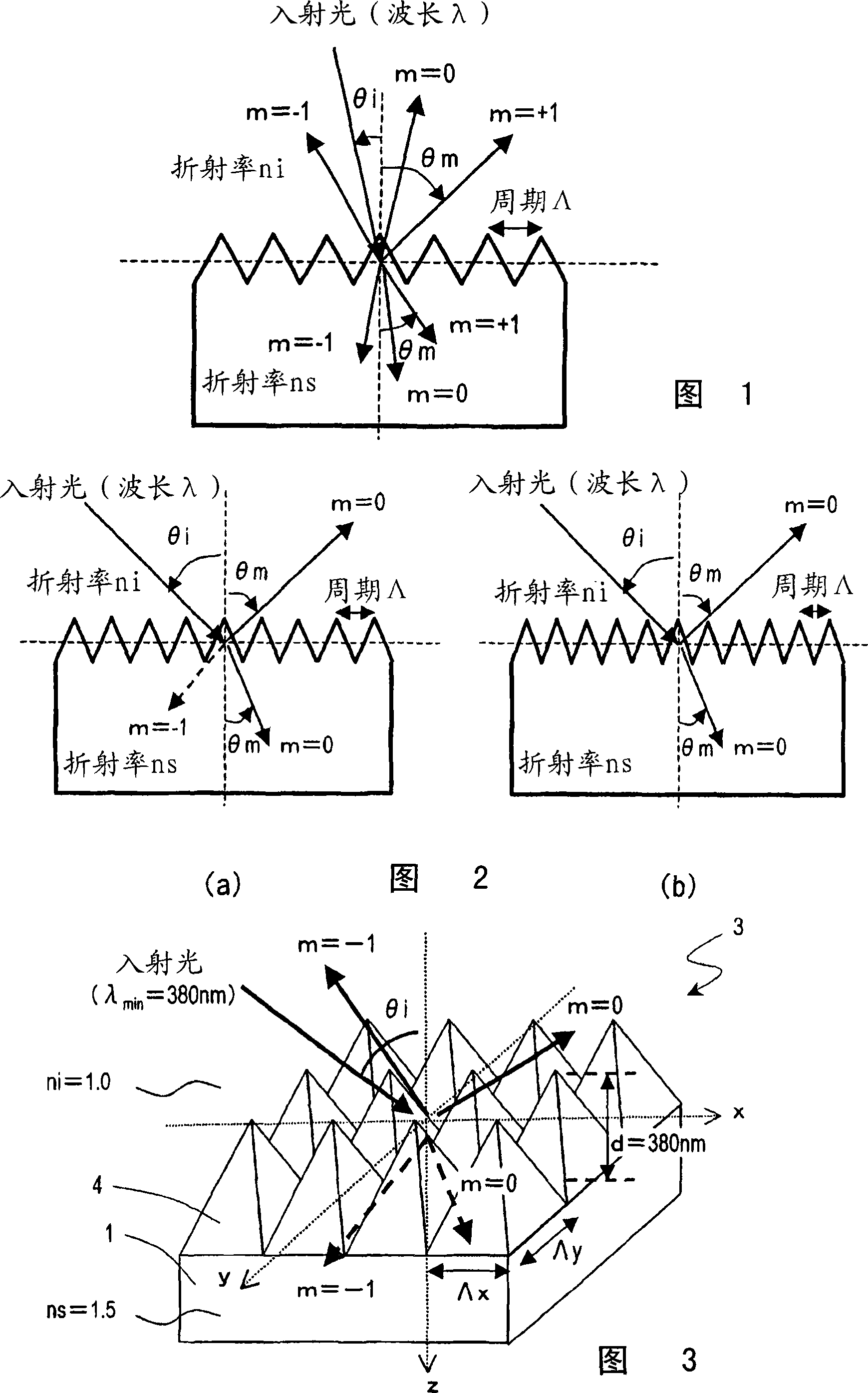
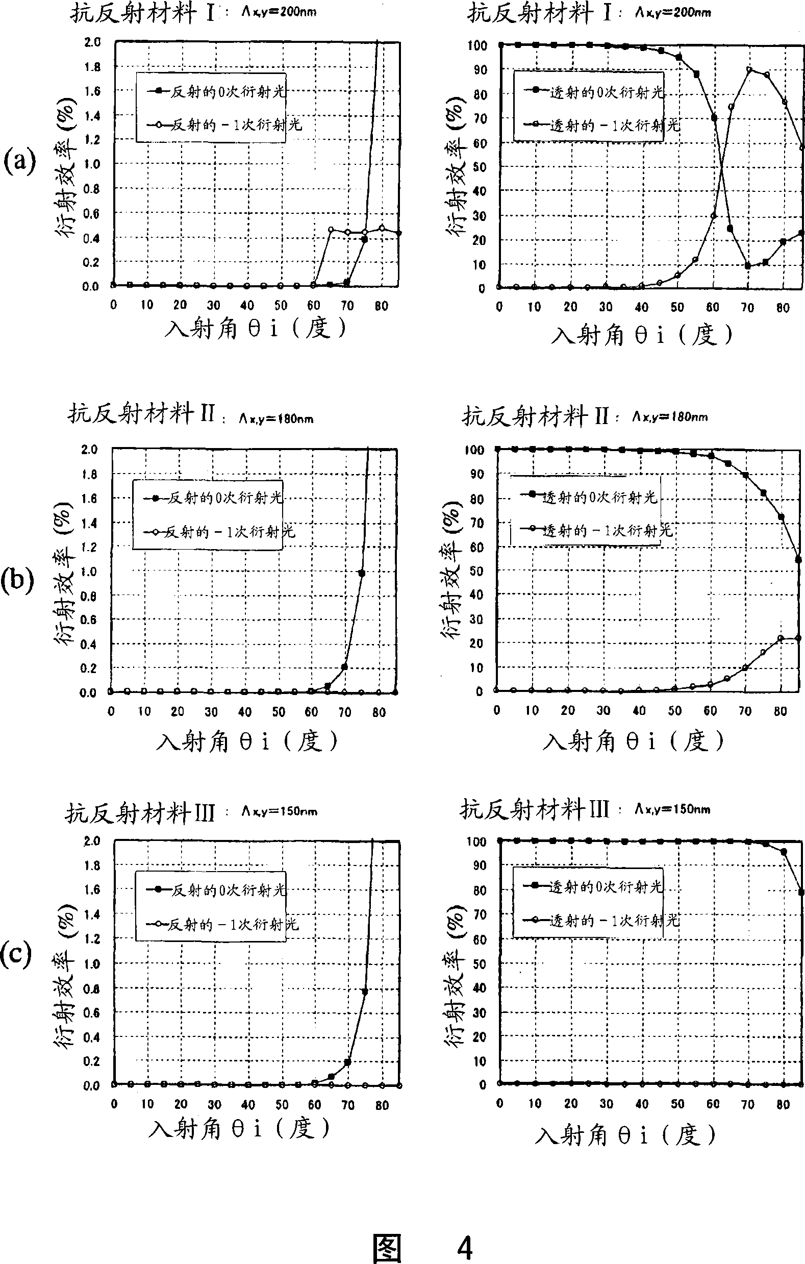
[0128] Hereinafter, a first embodiment of the antireflection material of the present invention will be described with reference to the drawings. The anti-reflection material of the present embodiment is an anti-reflection material in which a concavo-convex pattern whose period is smaller than the wavelength of the incident light is formed on the surface of the substrate. Assuming that the shortest wavelength of the incident light is λ min , the maximum incident angle of incident light is θi max , when the refractive index ni of the incident medium, the refractive index ns of the anti-reflection material, and the period of the x direction in the concave-convex pattern are Λx and the period of the y direction are Λy, the following formula (1) is satisfied. In addition, Λx and Λy are collectively described as "Λx, y".

[0129] [mathematical formula 5]

[0130] Λx , y λ min ...

Embodiment approach 2

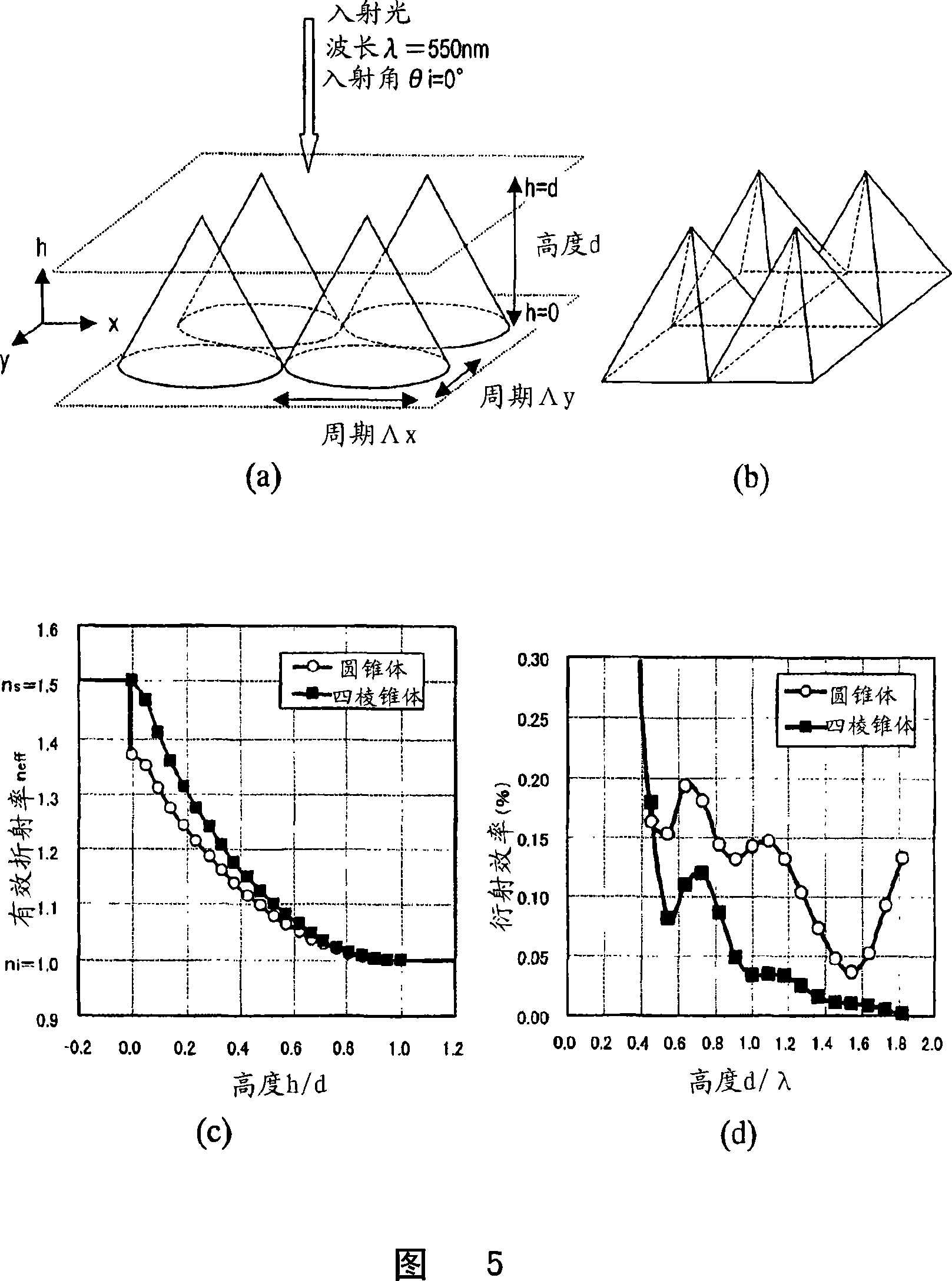
[0170] Next, a second embodiment of the antireflection material of the present invention will be described. The anti-reflection material in the present embodiment is to satisfy the above formula (1), preferably the anti-reflection material of the embodiment 1 satisfying the above formula (2), and assume that the coordinate axis of the height direction of the concave-convex pattern is the h axis, and the concave-convex pattern When the highest point of the convex portion in h=d and the lowest point of the concave portion in the concave-convex pattern is h=0, the effective refractive index n expressed as a function of h eff (h) also satisfies the following formula (3).

[0171] no eff (h=0)ns, and n eff (h=d)ni...(3)

[0172] The antireflection material of this embodiment can sufficiently suppress regular reflection (zero-order reflected diffracted light) from occurring.

[0173] The effective refractive index is determined by the occupancy rate (Fill Factor) of the irregu...

Embodiment approach 3

[0185] Next, a third embodiment of the antireflection material of the present invention will be described. The antireflection material of this embodiment is the antireflection material of Embodiment 2 satisfying the above formula (3), and the effective refractive index n eff (h) and use the following formula (5)

[0186] N eff (h)={(n eff (h=0)-n eff (h=d)) / d}×h+n eff (h=0)...(5)

[0187] The function represented by N eff (h) intersect at least at one point, and also satisfy the following formula (6).

[0188] | N eff (h)-n eff (h)|≤|n eff (h=d)-n eff (h=0)|×0.2...(6)

[0189] According to this embodiment, even if the normalized height represented by (d / λ) is made smaller than the antireflection material of Embodiment 2, the regular reflectance can be suppressed to 0.1% or less.

[0190] The effective refractive index n of the concave-convex shape expressed as a function of the height h of the concave-convex according to the above-mentioned requirements specified i...


PUM

PropertyMeasurementUnit
sizeaaaaaaaaaa
depthaaaaaaaaaa
refractive indexaaaaaaaaaa

Abstract

An antireflective member according to the present invention has an uneven surface pattern, in which unit structures are arranged in x and y directions at respective periods that are both shorter than the shortest wavelength of an incoming light ray, on the surface of a substrate and satisfies the following inequality (1): lambda, / lambda ) . . ., where lambda is the shortest wavelength of the incoming light ray, theta i is the largest angle of incidence of the incoming light ray, ni is the refractive index of an incidence medium, lambda is the period of the uneven surface pattern in the x direction, and lambda is the period of the pattern in the y direction. As a result, diffraction of short-wave light components can be reduced in a broad wavelength range.

Description

technical field [0001] The invention relates to an anti-reflection material with superior anti-reflection performance, an optical element and a display device equipped with the anti-reflection material. In addition, the present invention relates to a method of manufacturing a stamper (also referred to as a "metal mold" or "casting mold"), a method of manufacturing an antireflection material using the stamper, and an antireflection material. Background technique [0002] In optical elements such as display devices and camera lenses used in televisions and mobile phones, anti-reflection technology is generally implemented in order to reduce surface reflection and increase the amount of light transmitted. This is because, for example, when light is incident on the interface between air and glass, when light passes through the interface of a medium with a different refractive index, Fresnel reflection or the like is used to reduce the amount of light transmitted and reduce visib...

Claims


Application Information

Patent Timeline
Patent Type & Authority Applications(China)
IPC IPC(8): G02B1/11B32B7/02G02B1/118
Inventor 田口登喜生植木俊中村浩三津田和彦
Owner SHARP KK
Why Eureka
Try Eureka