Antireflective member, optical element, display device, method of making stamper and method of making antireflective member using the stamper
A manufacturing method and anti-reflection technology, applied in optical components, optics, instruments, etc., can solve the problems of insufficient anti-reflection effect, difficult metal molds, and difficulty in making large-area stamping molds.
- Summary
- Abstract
- Description
- Claims
- Application Information
AI Technical Summary
Problems solved by technology
Method used
Image
Examples
Embodiment approach 1
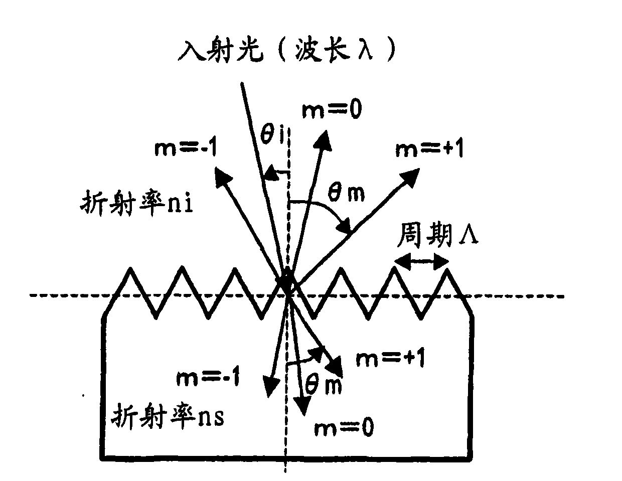
[0131] Hereinafter, a first embodiment of the antireflection material of the present invention will be described with reference to the drawings. The anti-reflection material of the present embodiment is an anti-reflection material in which a concavo-convex pattern whose period is smaller than the wavelength of the incident light is formed on the surface of the substrate. Assuming that the shortest wavelength of the incident light is λ min , the maximum incident angle of incident light is θi max , when the refractive index ni of the incident medium, the refractive index ns of the anti-reflection material, and the period of the x direction in the concave-convex pattern are Λx and the period of the y direction are Λy, the following formula (1) is satisfied. In addition, Λx and Λy are collectively described as "Λx, y".
[0132] [mathematical formula 5]
[0133] Λx , y λ min ...
Embodiment approach 2
[0173] Next, a second embodiment of the antireflection material of the present invention will be described. The anti-reflection material in the present embodiment is to satisfy the above formula (1), preferably the anti-reflection material of the embodiment 1 satisfying the above formula (2), and assume that the coordinate axis of the height direction of the concave-convex pattern is the h axis, and the concave-convex pattern When the highest point of the convex portion in h=d and the lowest point of the concave portion in the concave-convex pattern is h=0, the effective refractive index n expressed as a function of h eff (h) also satisfies the following formula (3).
[0174]
[0175] The antireflection material of this embodiment can sufficiently suppress regular reflection (zero-order reflected diffracted light) from occurring.
[0176] The effective refractive index is determined by the occupancy rate (Fill Factor) of the irregularities occupied in the incident medium (fo...
Embodiment approach 3
[0188] Next, a third embodiment of the antireflection material of the present invention will be described. The antireflection material of this embodiment is the antireflection material of Embodiment 2 satisfying the above formula (3), and the effective refractive index n eff (h) and use the following formula (5)
[0189] N eff (h)={(n eff (h=0)-n eff (h=d)) / d}×h+n eff (h=0)...(5)
[0190] The function represented by N eff (h) intersect at least at one point, and also satisfy the following formula (6).
[0191] |N eff (h)-n eff (h)|≤|n eff (h=d)-n eff (h=0)|×0.2...(6)
[0192] According to this embodiment, even if the normalized height represented by (d / λ) is made smaller than the antireflection material of Embodiment 2, the regular reflectance can be suppressed to 0.1% or less.
[0193] The effective refractive index n of the concave-convex shape expressed as a function of the height h of the concave-convex according to the above-mentioned requirements specified in...
PUM
| Property | Measurement | Unit |
|---|---|---|
| depth | aaaaa | aaaaa |
| refractive index | aaaaa | aaaaa |
| refractive index | aaaaa | aaaaa |
Abstract
Description
Claims
Application Information
 - R&D
- Intellectual Property
- Life Sciences
- Materials
- Tech Scout
- Unparalleled Data Quality
- Higher Quality Content
- 60% Fewer Hallucinations
Browse by: Latest US Patents, China's latest patents, Technical Efficacy Thesaurus, Application Domain, Technology Topic, Popular Technical Reports.
© 2025 PatSnap. All rights reserved.Legal|Privacy policy|Modern Slavery Act Transparency Statement|Sitemap|About US| Contact US: help@patsnap.com


