Replaceable clamp for electronic battery tester

a technology of electronic battery tester and clamp, which is applied in the direction of instruments, transportation and packaging, material analysis, etc., can solve the problems of failure of electronic battery tester and charger

Inactive Publication Date: 2009-10-06
MIDTRONICS
View PDF440 Cites 88 Cited by
  • Summary
  • Abstract
  • Description
  • Claims
  • Application Information

AI Technical Summary

Problems solved by technology

One source of failure in electronic battery testers and chargers are the clamps which are used to electrically couple the battery tester to terminals of storage batteries.

Method used


Image

  • Replaceable clamp for electronic battery tester
  • Replaceable clamp for electronic battery tester
  • Replaceable clamp for electronic battery tester

Examples


Embodiment Construction

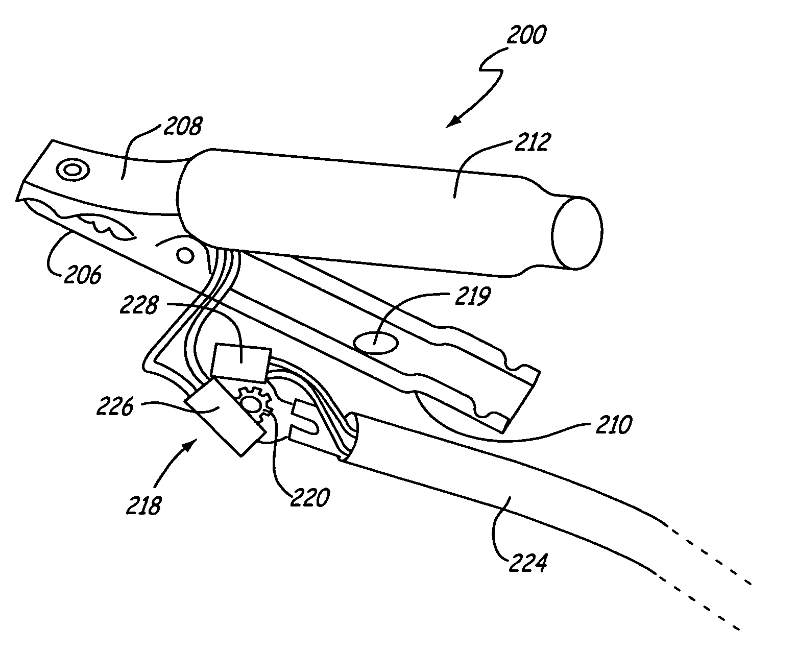
[0012]In the discussion below, the term “battery contact” is used to define a portion of the battery onto which the replaceable clamp of the present invention can be applied. The actual contact is an electrical contact and can be placed some distance from the battery.

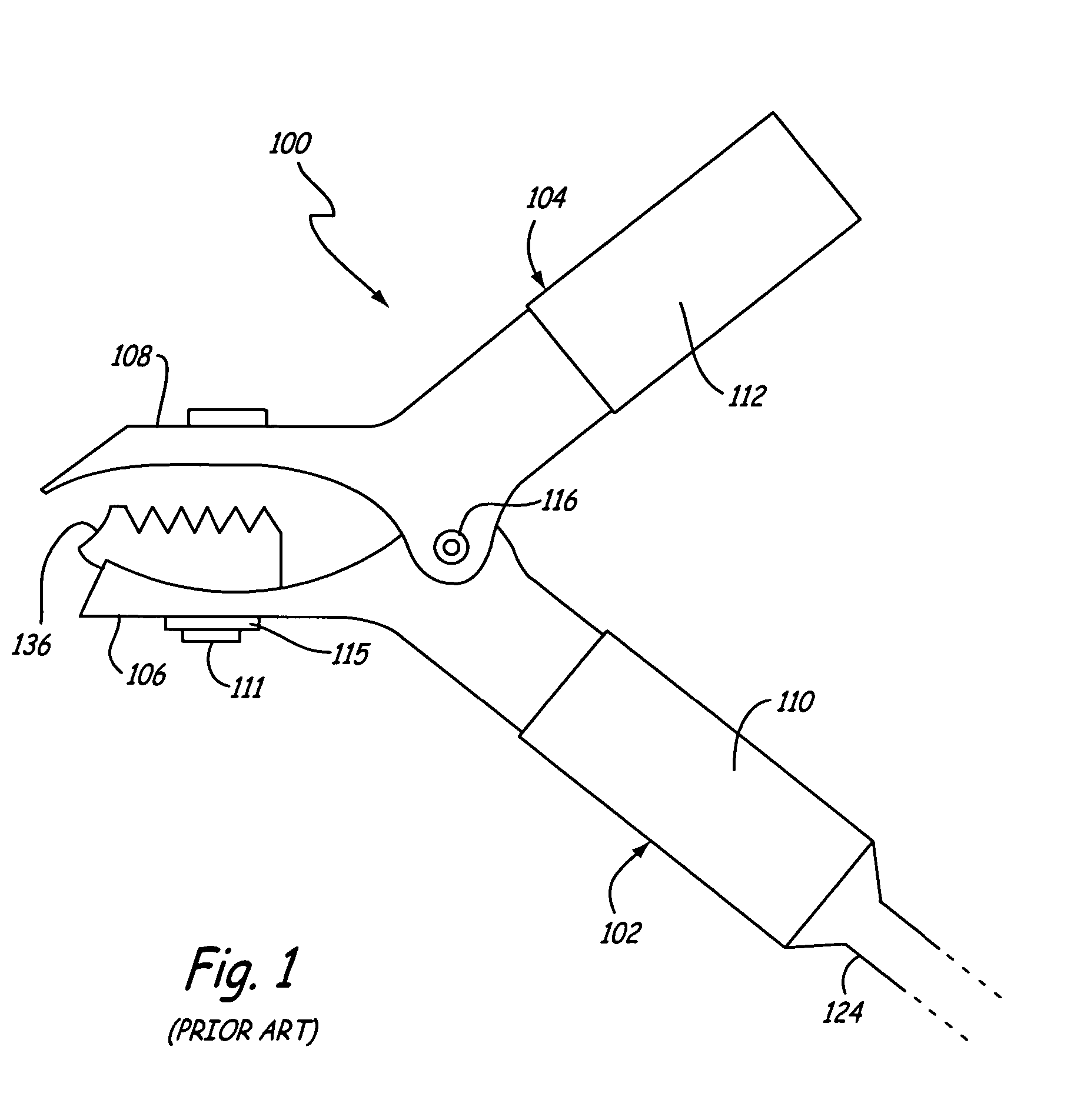
[0013]FIG. 1 is a side view of a Kelvin clamp 100 in accordance with the prior art. Clamp 100 includes first elongate clamp member 102 having a first jaw 106 and first hand grip 110 separated by a first coupling (hidden from view). Clamp 100 also includes second elongate clamp member 104 having a second jaw 108 and a second hand grip 112 separated by second coupling 116. Second elongate clamp member 104 is pivotally joined with first elongate clamp member 102 by second coupling 116 and the first coupling.

[0014]First elongate clamp member 102 is coupled to cable 124. Cable 124 includes a first electrical conductor (hidden from view) and a second electrical conductor (hidden from view), which are electrically isolated fro...


PUM


Abstract

A method and apparatus for coupling a battery charger and / or a battery tester to a battery is provided. A clamp can be selectively removed from a cable. This allows replacement of the clamp as desired as well as fixedly or removably coupling the cable to the battery tester or charger.

Description

BACKGROUND OF THE INVENTION[0001]The present invention relates to electronic battery testers and chargers of the type used to electrically test and charge storage batteries. More specifically, the present invention relates to clamps which are used to electrically couple such electronic battery testers and chargers to terminals of storage batteries.[0002]Storage batteries are used in many applications as sources of power. For example, storage batteries are used in automotive vehicles, both electrical vehicles and vehicles with internal combustion engines, as well as power supplies such as backup power systems. It is often desirable to measure the condition of such storage batteries. For example, it can be useful to determine the amount of charge a storage battery can hold (i.e. the capacity of the battery) or the state of health of a storage battery.[0003]A number of battery testing techniques are known in the art. These techniques include measuring the specific gravity of acid conta...

Claims


Application Information

Patent Timeline
Patent Type & Authority Patents(United States)
IPC IPC(8): H02J7/00G01R31/36
CPCG01R31/36G01R1/06788G01R31/3842G01R31/364H01R11/24
Inventor RESTAINO, HARVEY A.DEMEL, TIMOTHY PAULPIMENTEL, CHRISTIAN
Owner MIDTRONICS
Why Eureka
Try Eureka