Muzzle brake for cannon

a cannon and muzzle technology, applied in the field of muzzle brakes, can solve the problems of high load level, high amplitude and high frequency load, and high load level of muzzle brakes,

Inactive Publication Date: 2009-10-13
UNITED STATES OF AMERICA THE AS REPRESENTED BY THE SEC OF THE ARMY
View PDF17 Cites 23 Cited by
  • Summary
  • Abstract
  • Description
  • Claims
  • Application Information

AI Technical Summary

Problems solved by technology

The low number of baffles results in rapidly increasing muzzle brake forces, thereby producing high amplitude and high frequency loads due to the large area of the baffles and their few numbers.
Analysis of the M-284 muzzle brake shows very abrupt and high load levels from the first baffle of the muzzle brake.
As a result, the improperly designed geometries produce unsteady or oscillating flow fields in the supersonic flow environment.

Method used


Image

  • Muzzle brake for cannon
  • Muzzle brake for cannon
  • Muzzle brake for cannon

Examples


Embodiment Construction

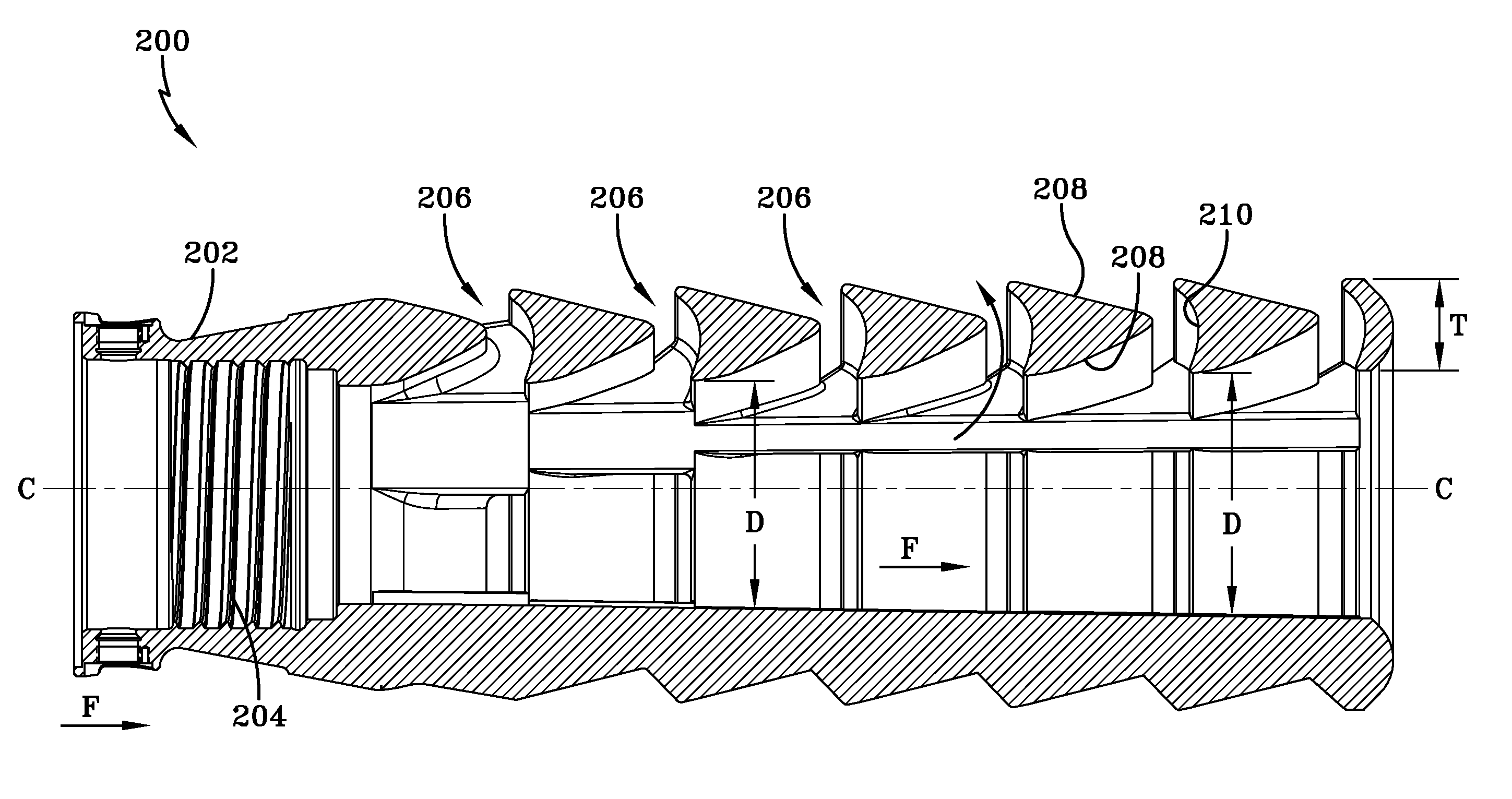
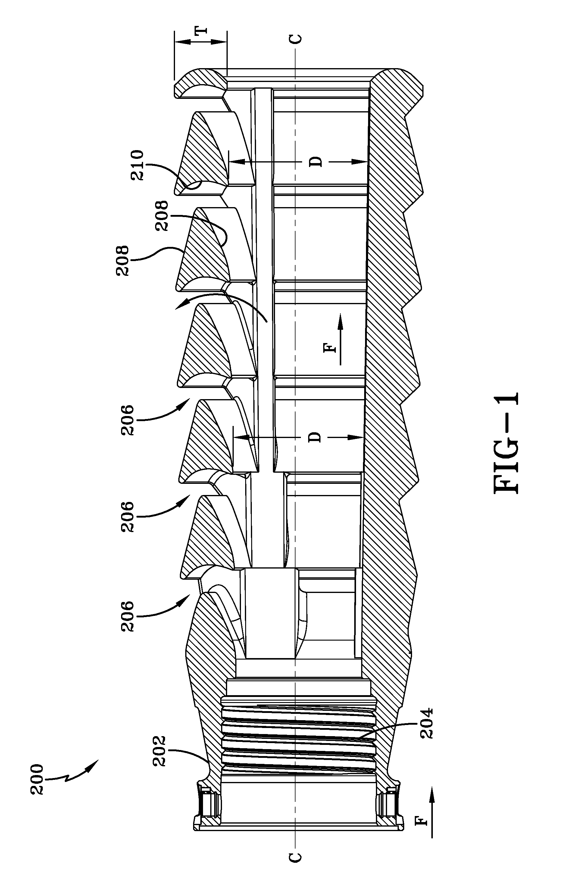
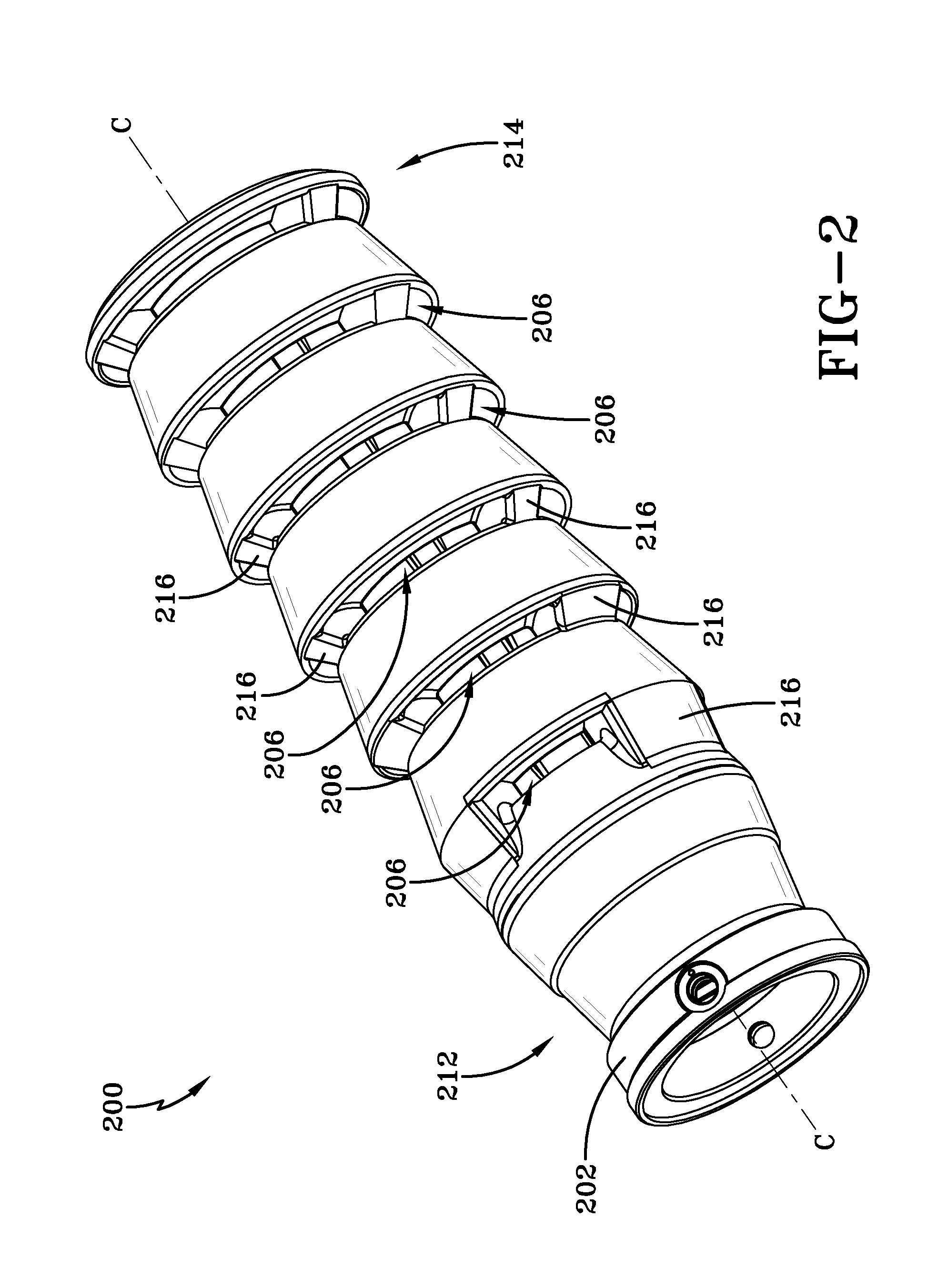
[0024]In the present invention, multiple turning vanes are used to spread muzzle brake loading out over time to reduce gun system high-frequency shock input. Compared to prior muzzle brakes, the invention uses smaller turning vanes, in larger numbers. As a result, the gun produces smaller increments of turning vane loading. Because pressure decreases from rear to front on a muzzle brake, it is desirable to use smaller vanes at the rear of the muzzle brake to produce more even loadings on the muzzle brake.

[0025]The invention encompasses a low-profile, high-efficiency muzzle brake. Higher efficiency reduces system weight and improves system integration. Given a maximum diameter for a muzzle brake, overall muzzle brake efficiency can be controlled by adding an appropriate number of vanes. The internal diameter of the vanes may be varied. A small internal diameter (less clearance around the projectile) is used at the rear of the brake and the internal diameter increases toward the front...


PUM


Abstract

A muzzle brake has a rear end, a front end and a central axis. The muzzle brake includes a plurality of axially spaced turning vanes; each turning vane having an inside diameter that is substantially equal to or greater than an inside diameter of a rearmost turning vane, at least one turning vane having an inside diameter that is greater than the inside diameter of the rearmost turning vane; and each turning vane having a thickness that is substantially equal to or greater than a thickness of the rearmost turning vane.

Description

CROSS-REFERENCE TO RELATED APPLICATIONS[0001]This application is a continuation-in-part of application Ser. No. 11 / 460,694 filed on Jul. 28, 2006. This application claims the benefit under 35 USC 119(e) of U.S. provisional patent application 60 / 595,912 filed on Aug. 16, 2005, which is hereby incorporated by reference.STATEMENT OF GOVERNMENT INTEREST[0002]The inventions described herein may be manufactured, used and licensed by or for the U.S. Government for U.S. Government purposes.BACKGROUND OF THE INVENTION[0003]The invention relates in general to munitions and in particular to muzzle brakes for gun tubes such as large caliber cannons, artillery, howitzers, tanks, and smaller caliber guns such as .50 caliber machine guns and guns carried by a one person.[0004]High-efficiency muzzle brakes used on large caliber weapons have low numbers (two or three) of baffles with relatively large areas. The low number of baffles results in rapidly increasing muzzle brake forces, thereby producin...

Claims


Application Information

Patent Timeline
Patent Type & Authority Patents(United States)
IPC IPC(8): F41A21/36
CPCF41A21/36
Inventor CLER, DANIEL L.FORLITI, DAVID
Owner UNITED STATES OF AMERICA THE AS REPRESENTED BY THE SEC OF THE ARMY
Why Eureka
Try Eureka