Perspective vertical situation display system and method

a vertical situation and display system technology, applied in the field of vehicles, can solve the problems that the two-dimensional display of terrain may not provide sufficient information for tactical, short-term flight planning and/or maneuvering

Active Publication Date: 2009-10-13
HONEYWELL INT INC
View PDF12 Cites 61 Cited by
  • Summary
  • Abstract
  • Description
  • Claims
  • Application Information

AI Technical Summary

Benefits of technology

[0007]The present invention provides a display system and method in which the terrain under the flight plan, or under the current track of the aircraft, is displayed in a manner that provides improved tactical flight planning, and / or that does not erroneously show the flight plan passing through the displayed terrain. In one embodiment, and by way of example only, a flight deck display system includes a processor and a display device. The processor is adapted to receive at least terrain data and is operable, in response thereto, to supply one or more image rendering display commands. The display device is coupled to receive the image rendering display commands and is operable, in response thereto, to simultaneously render a two-dimensional lateral situation view image representative of the terrain data and a perspective vertical situation view image representative of the terrain data.

Problems solved by technology

For example, the two-dimensional display of terrain may not provide sufficient information for tactical, short-term flight planning and / or maneuvering.
As such, the vertical situation display can erroneously indicate that the flight plan extends through the displayed terrain, if relatively high terrain is positioned to the left or right of the flight plan.

Method used


Image

  • Perspective vertical situation display system and method
  • Perspective vertical situation display system and method
  • Perspective vertical situation display system and method

Examples


Embodiment Construction

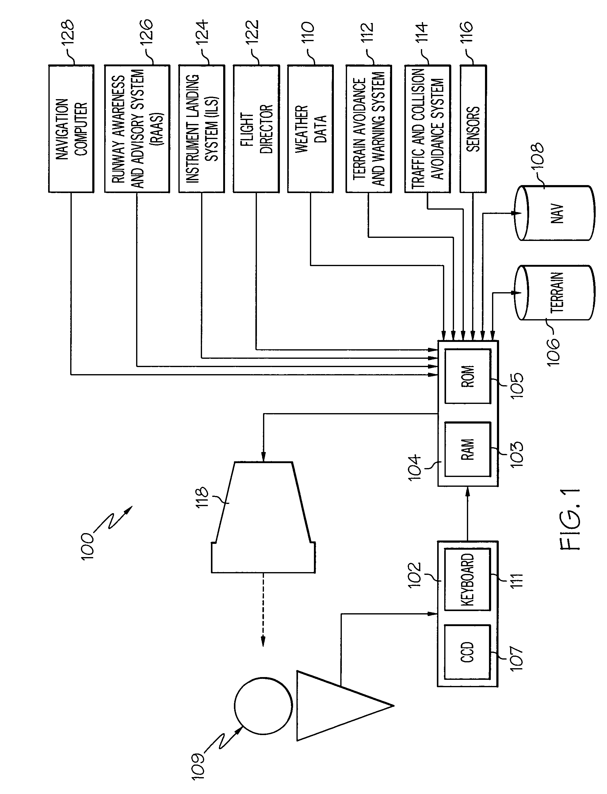
[0013]The following detailed description is merely exemplary in nature and is not intended to limit the invention or the application and uses of the invention. Furthermore, there is no intention to be bound by any expressed or implied theory presented in the preceding technical field, background, brief summary or the following detailed description.

[0014]The present invention may be described in terms of functional block diagrams and various processing steps. It should be appreciated that such functional blocks may be realized in many different forms of hardware, firmware, and / or software components configured to perform the various functions. For example, the present invention may employ various integrated circuit components, e.g., memory elements, digital signal processing elements, look-up tables, and the like, which may carry out a variety of functions under the control of one or more microprocessors or other control devices. Such general techniques are known to those skilled in ...


PUM


Abstract

A display system and method for an aircraft simultaneously displays the terrain under the flight plan, or under the current track of the aircraft, as both a two-dimensional lateral situation view image and as a perspective vertical situation view image. This provides improved tactical flight planning, and that does not erroneously show the flight plan passing through the displayed terrain.

Description

CROSS-REFERENCE TO RELATED APPLICATIONS[0001]This application claims the benefit of U.S. Provisional Application Ser. No. 60 / 525,408, filed Nov. 25, 2003.TECHNICAL FIELD[0002]The present invention relates to a display for a vehicle and, more particularly, to a system and method for displaying a perspective view of terrain information in an aircraft vertical situation display.BACKGROUND[0003]Modem map displays, particularly those used in aircraft for flight planning and monitoring, are capable of displaying a considerable amount of information such as weather information and terrain information. The weather information consists of airborne weather information from onboard weather radar or weather information received from, for example, ground based or satellite weather sources.[0004]Most modern displays additionally allow an aircraft flight plan to be displayed from two different views, either a lateral view or a vertical view, which can be displayed individually or simultaneously on...

Claims


Application Information

Patent Timeline
Patent Type & Authority Patents(United States)
IPC IPC(8): G01C21/10G05D1/08G06F19/00B64C1/00G01C21/30G01C23/00G08G5/00G08G5/02G09B9/05G09B29/00
CPCG01C23/00G08G5/0013G08G5/0021G09B29/007G08G5/0086G09B9/05G08G5/0052
Inventor DWYER, DAVID B.NICHOLS, TROY A.HILBERT, MATTHEWLITTLE, MICHAEL C.
Owner HONEYWELL INT INC
Why Eureka
Try Eureka