Optical reading head of scanning apparatus

a scanning apparatus and reading head technology, applied in the direction of instruments, sensing record carriers, electromagnetic radiation sensing, etc., can solve the problems of easy slope right or left inability to move stably along the gliding pedestal, and the adjustable mechanism of the optical path, so as to increase the accumulated tolerance of the optical reading head

Active Publication Date: 2009-10-20
INTELLECTUAL VENTURES I LLC
View PDF11 Cites 7 Cited by
  • Summary
  • Abstract
  • Description
  • Claims
  • Application Information

AI Technical Summary

Benefits of technology

[0008]As previously described, in the optical reading head of the conventional scanning apparatus, the lens is mounted on the base. Since the lens is indirectly moved on the casing via the base to perform the focusing and magnification correcting operations, the accumulated tolerance of the optical reading head is increased.
[0010]It is an object of the present invention to provide an optical reading head of a scanning apparatus for minimizing the accumulated tolerance.
[0012]It is a further object of the present invention to provide an optical reading head of a scanning apparatus, which has an improved base capable of fixing a lens thereon and is easily detachable when the optical reading head is maintained and reworked and the lens needs to be replaced

Problems solved by technology

This optical path adjustable mechanism, however, has some drawbacks.
Unfortunately, since the pushing force applied by the resilient element sheet is perpendicular to the advancing direction, the base is readily sloped rightwards or leftwards and fails to be stably moved along the gliding pedestal.

Method used


Image

  • Optical reading head of scanning apparatus
  • Optical reading head of scanning apparatus
  • Optical reading head of scanning apparatus

Examples


Embodiment Construction

[0028]The present invention will now be described more specifically with reference to the following embodiments. It is to be noted that the following descriptions of preferred embodiments of this invention are presented herein for purpose of illustration and description only. It is not intended to be exhaustive or to be limited to the precise form disclosed. The schematic drawings, not to scale, are employed to illustrate the specific features of the present invention. In addition, the elements or structures in the drawings are not limited to the precise form disclosed. Unless specifically stated, the individual element may be extensive to include multiple elements or structures.

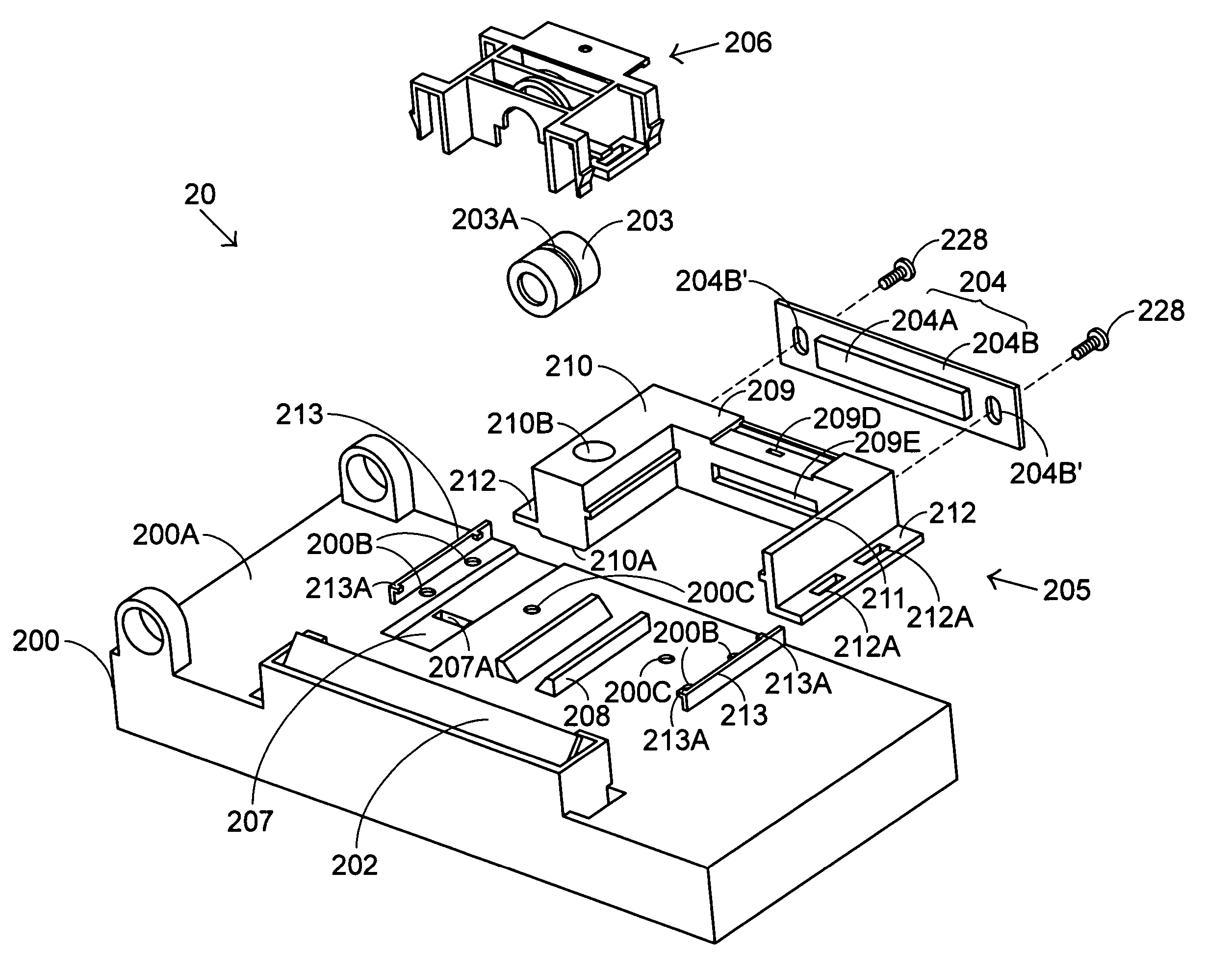
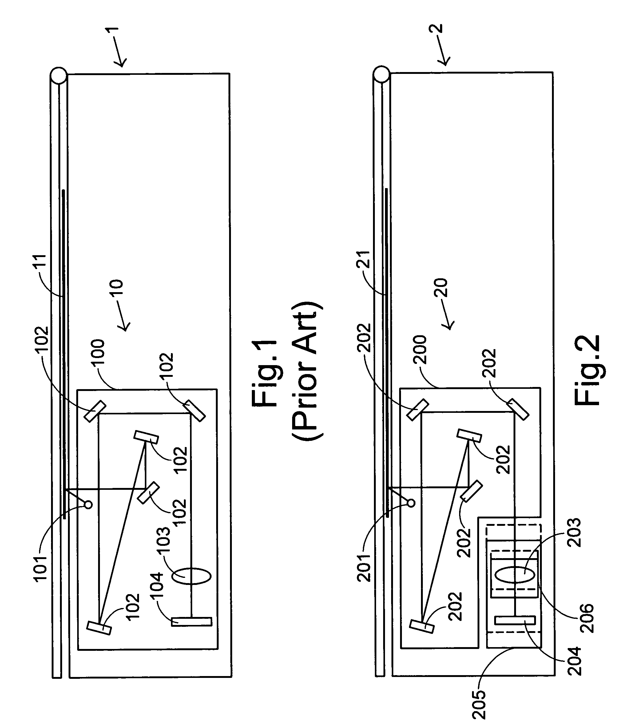
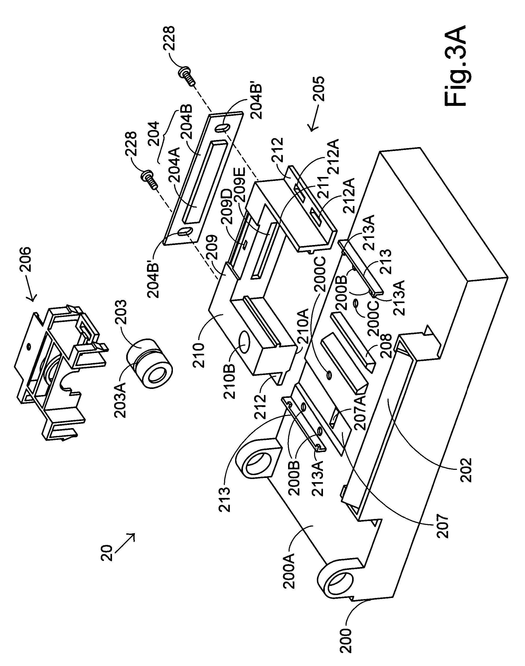
[0029]Referring to FIG. 2, a schematic cross-sectional view of an optical reading head of a scanning apparatus according to a preferred embodiment of the present invention is shown. The optical reading head 20 of the scanning apparatus 2 comprises a light source 201, plural reflective mirrors 202, a lens 203...


PUM


Abstract

An optical reading head of a scanning apparatus includes a casing, a lens, a base and a sliding frame. The base is used to support an image sensing module and movable on the casing. The sliding frame is coupled with the base for fixing and driving the lens to move along a gliding track on the casing. During the focusing operation, the lens' position is adjustable by moving the sliding frame and the optical signals are clearly imaged onto the image sensor of the imaging sensing module. During the magnification correcting operation, positions of the lens and the imaging sensing module are adjustable by moving the base and the tolerance of magnification for the optical reading head would be equal to or less than an acceptable preset value.

Description

FIELD OF THE INVENTION[0001]The present invention relates to an optical reading head of a scanning apparatus, and more particularly to an optical reading head having a sliding frame and a base for facilitating the assembler to perform focusing and magnification correcting operations.BACKGROUND OF THE INVENTION[0002]Referring to FIG. 1, a schematic cross-sectional view of an optical reading head of a conventional scanning apparatus 1 is illustrated. The optical reading head 10 comprises a light source 101, plural reflective mirrors 102, a lens 103 and an image sensing module 104 are provided. During operation, the light emitted from the light source 101 is projected onto a document 11 to be scanned. The light reflected from the scanned document 11 is successively reflected by the plural reflective mirrors 102, and then focused by the lens 103. The focused light is then imaged onto an image sensor (not shown) of the image sensing module 104 to convert the optical signals into analog e...

Claims


Application Information

Patent Timeline
Patent Type & Authority Patents(United States)
IPC IPC(8): G06K7/10
CPCH04N1/00559H04N1/02409H04N1/1013H04N2201/0458H04N2201/02402
Inventor CHANG, YU-CHENG
Owner INTELLECTUAL VENTURES I LLC
Why Eureka
Try Eureka