Fastener assembly

a technology of fasteners and parts, applied in the field of fasteners, can solve the problems of high labor intensity, high cost, and labor-intensive process of attaching objects to the frame, and achieve the effect of facilitating movement of the elongated body

Active Publication Date: 2009-10-20
EATON INTELLIGENT POWER LTD
View PDF9 Cites 54 Cited by
  • Summary
  • Abstract
  • Description
  • Claims
  • Application Information

AI Technical Summary

Benefits of technology

[0006]In another embodiment, a fastener assembly of this invention comprises an elongate body having a first face constituting an inside face, an opposite face constituting an outside face, opposite sides, and opposite ends. The assembly also includes a washer having a first face constituting an inside face opposing and spaced from the outside face of the elongate body, and a second face constituting an outside face. An opening extends through the washer. A resiliently deformable element is interposed between the elongate body and the washer. The resiliently deformable element has a first end affixed to the elongate body and a second end affixed to the washer. The resiliently deformable element urges the elongate body and washer toward one another and permits relative movement between the elongate body and the washer. At least one ramp is provided on the elongate body to facilitate movement of the elongate body away from the washer during installation.

Problems solved by technology

This installation process, using a nut and a separate washer, by the person attaching the object to the framing is relatively labor intensive and thus expensive.

Method used


Image

  • Fastener assembly
  • Fastener assembly
  • Fastener assembly

Examples


Embodiment Construction

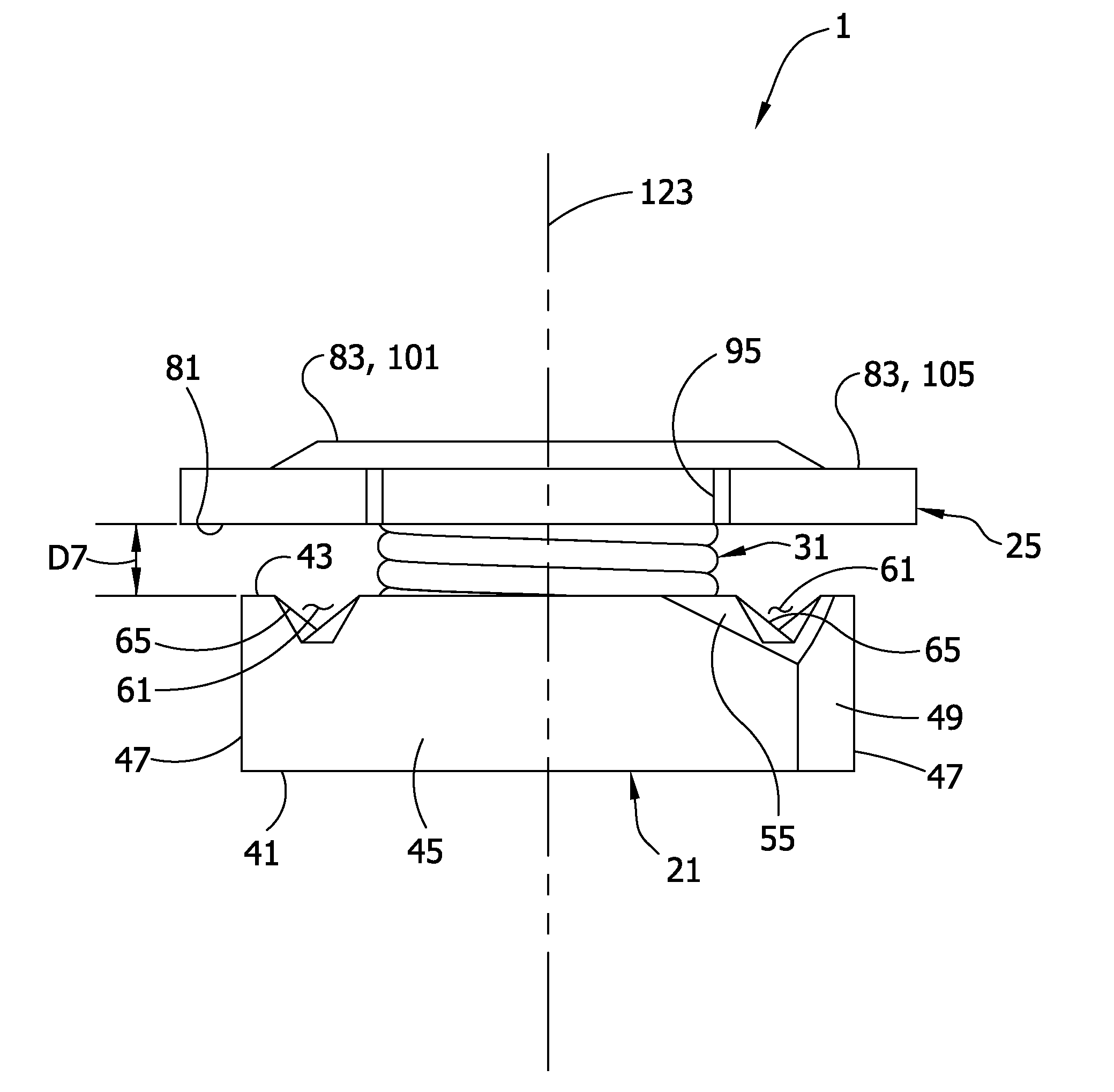
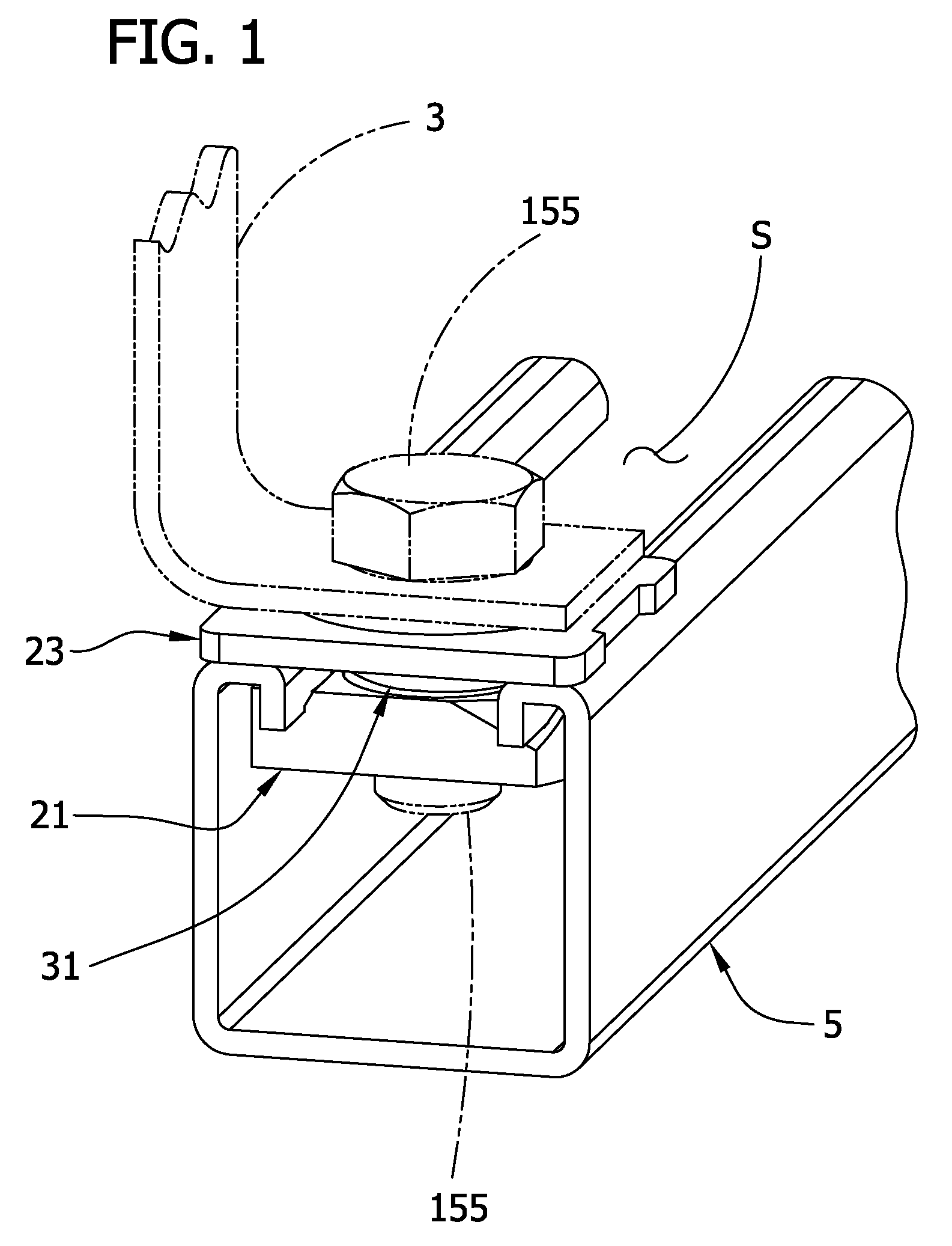
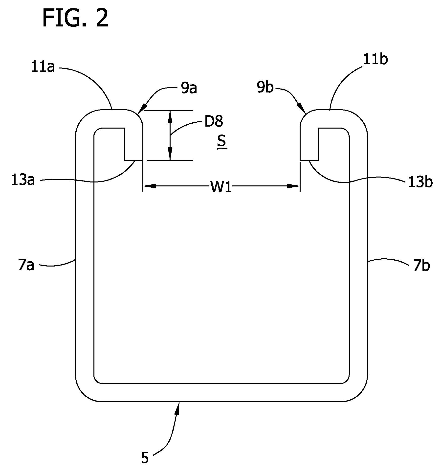
[0021]Referring now to the drawing, particularly to FIG. 1, a fastener assembly of this invention is indicated in its entirety at 1. The assembly 1 is used to secure an object 3 (such as the bracket shown in phantom in FIG. 1) to a structure such as metal framing 5 which, in one embodiment, comprises a channel-shaped support sometimes referred to as “strut.” As shown in FIG. 2, the channel 5 has a pair of side flanges 7a, 7b, the outer (upper) ends of which have inwardly directed lips formed thereon as indicated generally at 9a and 9b. These lips are hook-shaped, having outside faces 11a, 11b and inside faces defined by edges 13a, 13b. The lips are spaced from one another to define a slot S which extends the length of the channel. The slot has a width W1. The framing 5 may have other shapes. Further, a fastener assembly of this invention can be used to secure an object 3 to other types of structures.

[0022]In general, the fastener assembly comprises three parts (see FIG. 3). The firs...


PUM


Abstract

A fastener assembly is disclosed for securing an object to channel framing. One embodiment of the assembly includes an elongate body such as a nut which engages inside faces of the framing at opposite sides of a slot in the framing, a washer spaced from the nut which engages outside faces of the framing at opposite sides of the slot, and a spring interposed between and connecting the nut and the washer for generating a force holding the washer and nut in clamping engagement with respective faces of the framing prior to securing an object to the framing.

Description

BACKGROUND OF THE INVENTION[0001]This invention relates generally to fasteners for fastening objects to metal channel framing and, more particularly, to a fastener assembly in which an elongate body (e.g., a nut with a threaded opening), a washer and a spring are pre-assembled to reduce the time needed to assemble and install such items on framing at the job site.[0002]Electrical conduit, pipes, fixtures, etc. are commonly supported overhead or vertically by channel framing conventionally having side flanges with inwardly turned, hook-shaped lips defining a slot extending lengthwise of the framing. Typically, an elongate nut with a threaded opening is used for securing objects to the framing, the nut first being aligned with, entered into and passed through the slot, and then turned 90 degrees to a crosswise position with the outside face of the nut engaging the inside faces of the channel lips. Various mechanisms are used for holding the nut against the channel in its crosswise pos...

Claims


Application Information

Patent Timeline
Patent Type & Authority Patents(United States)
IPC IPC(8): F16B27/00
CPCF16B37/046
Inventor WU, XIAODONG
Owner EATON INTELLIGENT POWER LTD
Why Eureka
Try Eureka