Expandable slip ring

a slip ring and expansion technology, applied in the field of rings, can solve the problems of structural integrity, behavior of the slip ring during expansion, and the detriment of the built-in flexibility of the prior design, and achieve the effect of enhancing the integrity of the slip ring

Active Publication Date: 2009-10-27
BAKER HUGHES INC
View PDF16 Cites 61 Cited by
  • Summary
  • Abstract
  • Description
  • Claims
  • Application Information

AI Technical Summary

Benefits of technology

[0006]An expandable slip ring is used to secure attachment of an expanded tubular to a surrounding tubular. It features elongated generally axially oriented openings separated by narrow segments. As a swage is advanced within a tubular that has the slip ring outside it the narrow segments or tabs expand and can break but the ring is still held to its shape as the expansion progresses due to the integrity of other tabs that can subsequently break as the swage advances within the tubular that is surrounded by the slip ring. The integrity of the slip ring is enhanced for storage and run in while the expansion characteristics are more uniform as the ring retains some structural integrity during much of the expansion process.

Problems solved by technology

While that was true, there were other issues with such a design.
One issue was structural integrity during storage, when no pipe extended through the slip ring, and later on when running the slip ring into the well on a tubular.
The built in flexibility of the prior design proved to be a detriment in those situations.
Another issue was the behavior of the slip ring during expansion.
Due the flexible nature of the design, as the tubular inside was expanded with a swage the growth in dimension of the slip ring was irregular resulting in unsymmetrical contact with the surrounding tubular as the swage was advanced.
This tendency of irregular expansion decreased the support capability of the connection after expansion and in extreme situations prevented a fluid tight connection from occurring.

Method used


Image

  • Expandable slip ring
  • Expandable slip ring
  • Expandable slip ring

Examples


Embodiment Construction

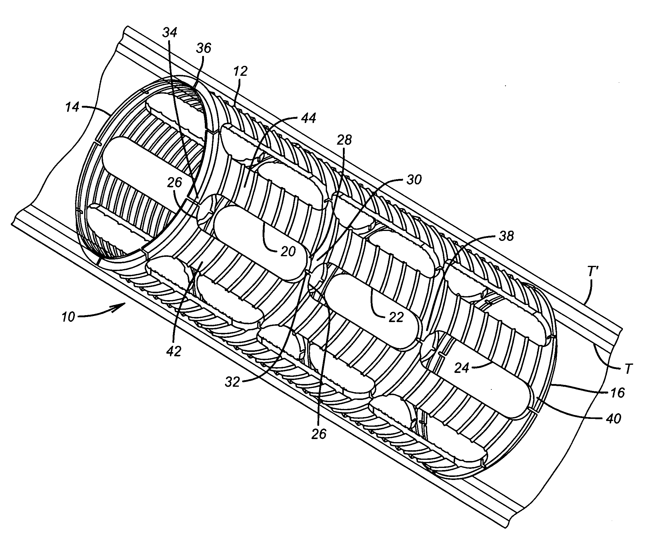
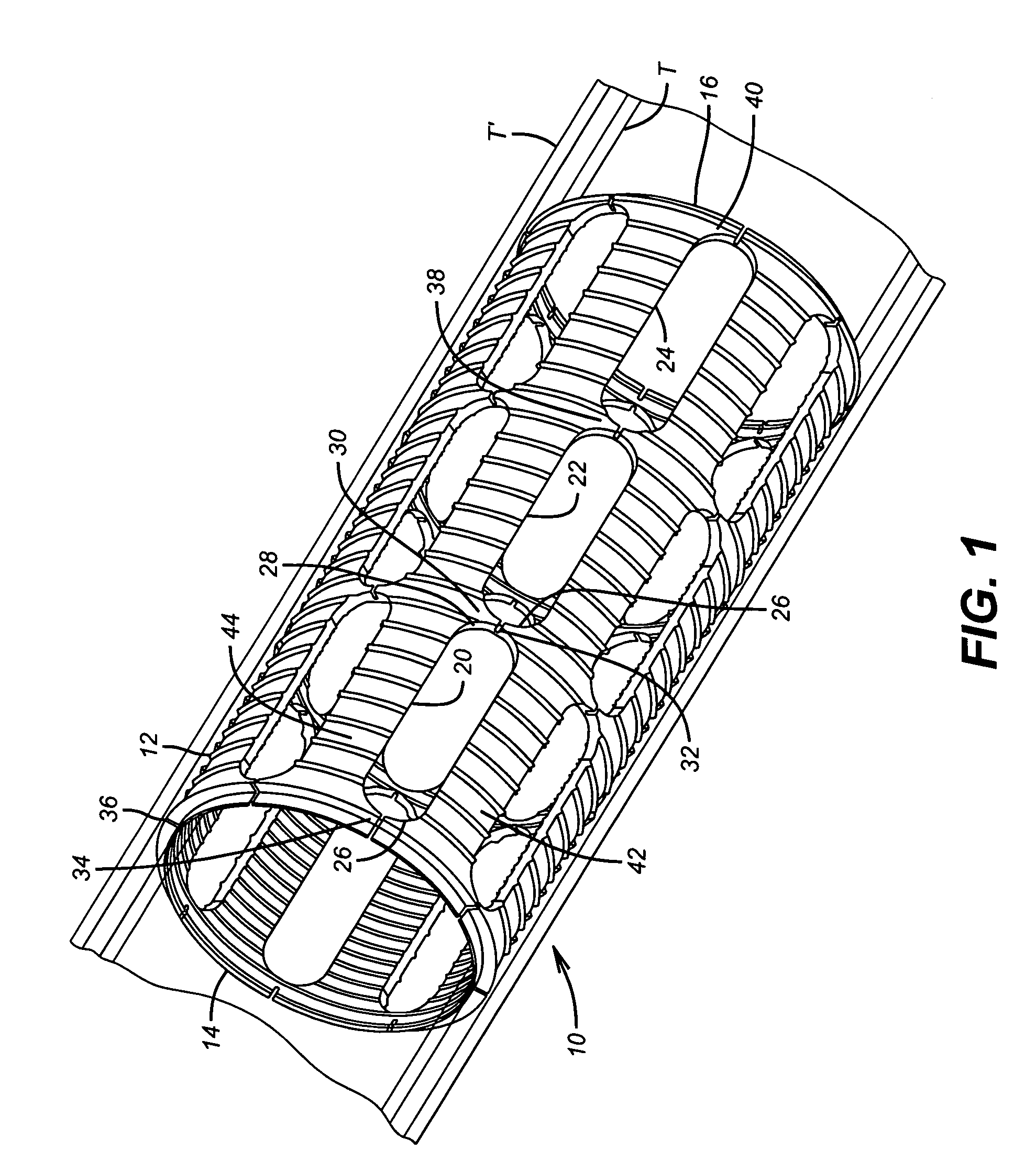
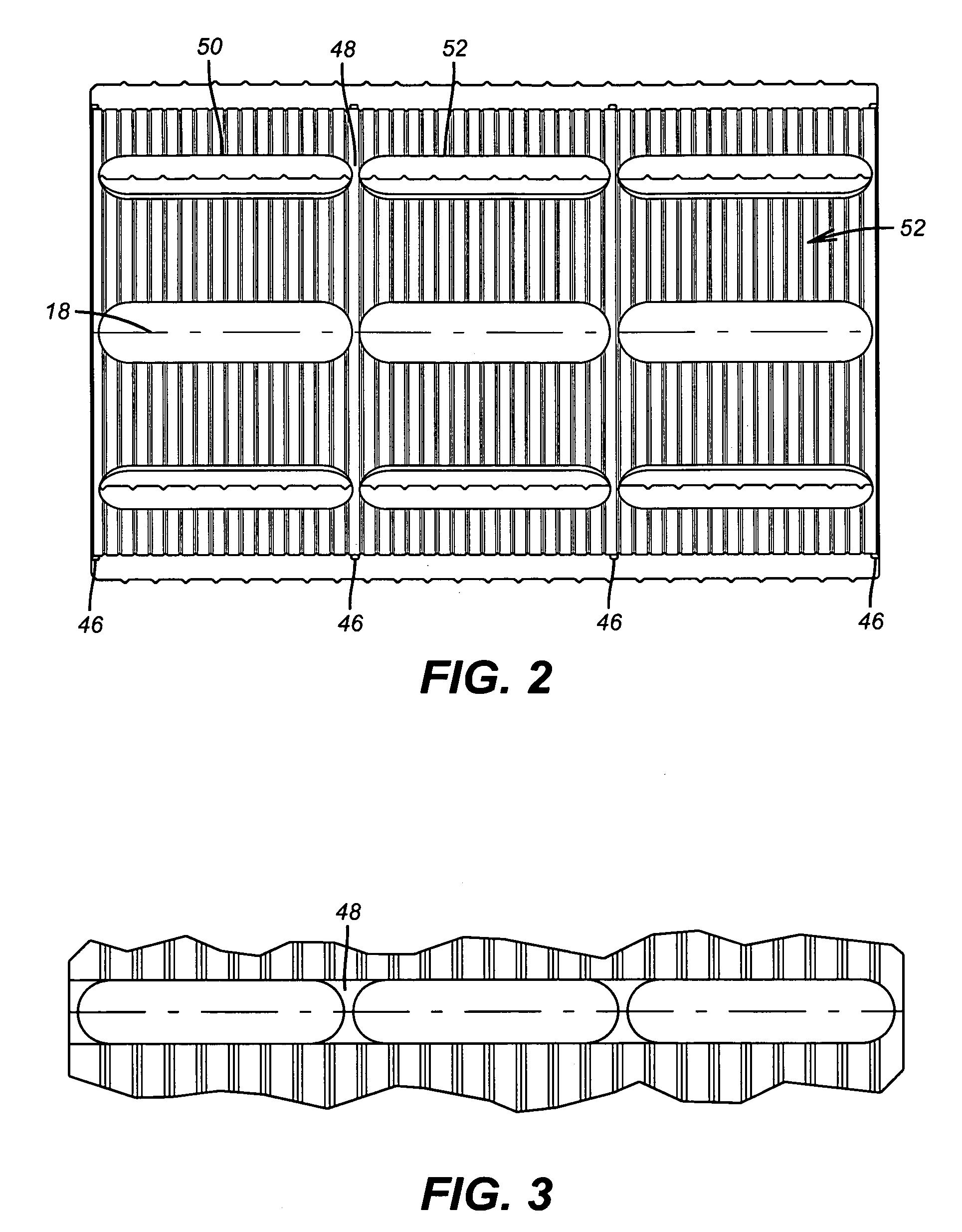
[0010]FIG. 1 shows a unitary, or made of one piece, slip ring 10 in perspective. It features external serrations 12 that are shown as a series of axially spaced rings but other patterns can be used to enhance grip or even random distribution of projections that act as grip enhancers without departing from the invention. The slip ring 10 has opposed ends 14 and 16. A longitudinal axis 18 is shown in the embodiment of FIG. 2. As shown in FIG. 1 a series of openings 20, 22 and 24 are preferably generally aligned with each other in rows and with longitudinal axis 18. Each opening such as 20 is preferably axially aligned and circumferentially spaced from the other openings 20. In the preferred embodiment the openings are equally spaced circumferentially at a given axial location. In the preferred embodiment the other openings 22 and 24 are similarly oriented with regard to like openings adjacent to them. The openings are preferably elongated slots with rounded ends such as 26 and 28 at o...


PUM


Abstract

An expandable slip ring is used to secure attachment of an expanded tubular to a surrounding tubular. It features elongated generally axially oriented openings separated by narrow segments. As a swage is advanced within a tubular that has the slip ring outside it the narrow segments or tabs expand and can break but the ring is still held to its shape as the expansion progresses due to the integrity of other tabs that can subsequently break as the swage advances within the tubular that is surrounded by the slip ring. The integrity of the slip ring is enhanced for storage and run in while the expansion characteristics are more uniform as the ring retains some structural integrity during much of the expansion process.

Description

FIELD OF THE INVENTION[0001]The field of the invention is rings that are expanded with a tubular into a surrounding tubular for support.BACKGROUND OF THE INVENTION[0002]Strings of tubulars are frequently supported from surrounding tubulars already run into the wellbore. One way to do that is to set a packer with slips that bite the surrounding tubular and a seal assembly to seal the annular space. Another way to do this is to expand the smaller tubular into a larger surrounding tubular into which it has been run. When so doing, a slip ring delivered on the smaller tubular is employed. As the smaller tubular is expanded, the slip ring is expanded as well until the slip ring contacts the surrounding tubular. At that time the slip ring can get a bite into the surrounding tubular to enhance the connection and to increase the support capacity of the connection.[0003]Prior slip ring designs involved cylindrical shapes that were an open undulating structure of spaced axially oriented eleme...

Claims


Application Information

Patent Timeline
Patent Type & Authority Patents(United States)
IPC IPC(8): E21B23/00
CPCE21B43/106E21B23/00
Inventor TOM, ANDYFRASER, JAMES M.BAUGH, JOHN L.
Owner BAKER HUGHES INC
Why Eureka
Try Eureka