LED light string with split bridge rectifier and thermistor fuse

a technology of rectifier and thermistor fuse, which is applied in the field of strings of lights, can solve the problems of easy burns, decorated, and shorted led heat up enough to become a fire hazard,

Active Publication Date: 2009-10-27
BEST POINT GROUP LTD
View PDF42 Cites 115 Cited by
  • Summary
  • Abstract
  • Description
  • Claims
  • Application Information

AI Technical Summary

Benefits of technology

[0011]The advantage of the split bridge rectifier is that it allows the circuit to deliver alternating current to the receptacle and DC to the LED load but with less conducting wire than would be required for an LED light string that had the rectifier in the receptacle because the wires used for delivering the AC to the receptacle can be used as part of the bridge.

Problems solved by technology

In the event one or more of the LEDs in the series shorts, the shorted LED may heat up enough to become a fire hazard, as LEDs melt at a relatively low temperature.
Furthermore, LEDs are often used to decorate artificial trees which, particularly when decorated, can burn readily.

Method used


Image

  • LED light string with split bridge rectifier and thermistor fuse
  • LED light string with split bridge rectifier and thermistor fuse

Examples


Embodiment Construction

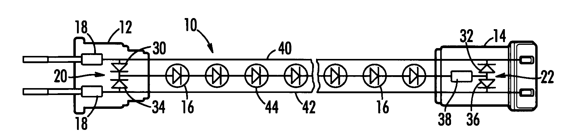
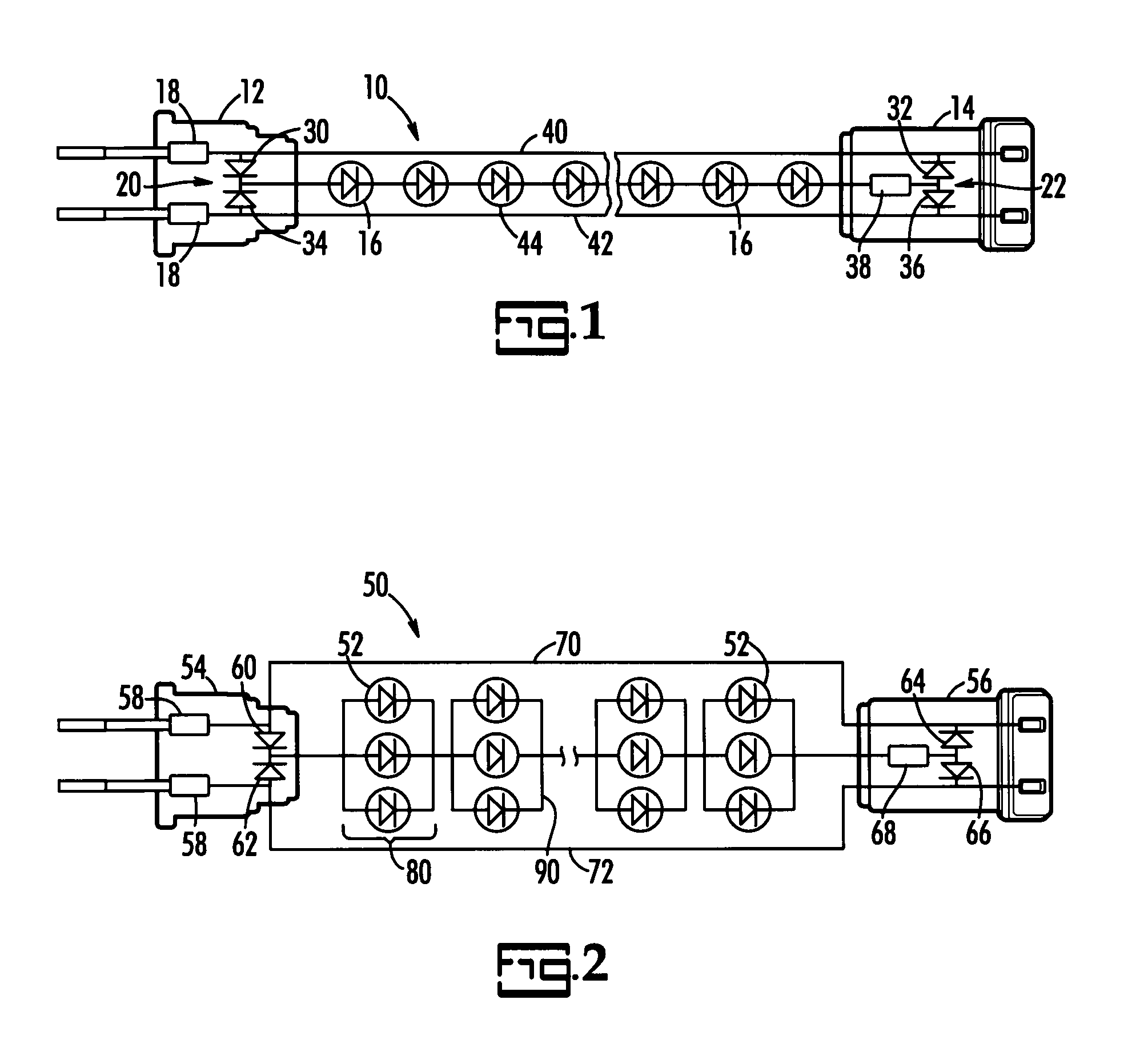
[0017]The present invention is a light string, such as might be used for holiday decorating. The present light string preferably uses plural light-emitting diodes (LEDs) rather than incandescent lights with the LEDs arranged in an electrical series with each other. A negative temperature coefficient (NTC) thermistor is placed in series with the LEDs. Alternatively, LEDs, as will be further described below, are arranged in groups of two or more electrically parallel LEDs are arranged electrically in series with each other group and with an NTC thermistor. Most preferably, when this series / parallel arrangement is used, a device is also placed in parallel with each group to regulate voltage in the event any of the LEDs in that group burn out or are lost, as described in U.S. Pat. No. 6,367,957, which is incorporated herein in its entirety.

[0018]Referring now to FIG. 1, at one end of a light string 10 is a plug 12 adapted for connecting to a source of alternating electrical current (AC)...


PUM


Abstract

A string of lights has an electrical plug at one end and a receptacle at the other end and plural light-emitting diodes (LEDs) in series with a negative temperature coefficient (NTC) thermistor. The device also includes a bridge rectifier providing direct current to the LEDs and the thermistor but split between the plug and receptacle of the light string so that alternating current from the plug is delivered to the receptacle but direct current flow through the LEDs. Light string fuses protect the string but the NTC fuses protect the LEDs at a lower current rating. The LEDs can be arranged in a simple electrical series, or, in an alternative embodiment, an electrical series of groups of plural LEDs each of which is arranged electrically in parallel with other LEDs of the same group. The use of the lower-current-rating NTC thermistor allows the LEDs in one light string to fail without necessarily jeopardizing the current flow to subsequent light strings unless the current is high enough to blow the light string fuses in the plug.

Description

CROSS REFERENCE TO RELATED PATENTS[0001]The priority benefit of U.S. provisional patent application Ser. No. 61 / 029,464, filed Feb. 18, 2008, is claimed, which application is incorporated herein in its entirety by reference.BACKGROUND OF THE INVENTION[0002]The present invention relates to strings of lights used for decorating during holiday times.[0003]Typical light strings consist of plural lamps electrically wired together in series or in parallel. There is an electrical plug at one end of the string adapted for being inserted into a wall socket or other source of electricity, and a receptacle at the other end adapted to receive a plug from a second light string and to deliver electricity to a second light string. Most lights strings operate on alternating, household current. More recently, some light strings have been made to operate on direct current produced by a rectifier placed in the plug or in the receptacle, as disclosed, for example, by the present applicant in U.S. Pat. ...

Claims


Application Information

Patent Timeline
Patent Type & Authority Patents(United States)
IPC IPC(8): H05B37/00
CPCH05B33/0803H05B33/0809F21S4/003Y02B20/348Y02B20/341F21S4/20H05B45/00Y02B20/30H05B45/40
Inventor GIBBONEY, JAMES W.
Owner BEST POINT GROUP LTD
Why Eureka
Try Eureka