Inkjet nozzle assembly having thermal bend actuator with an active beam defining part of an exterior surface of a nozzle chamber roof

a technology of thermal bend actuator and active beam, which is applied in the direction of printing, inking apparatus, etc., can solve the problems of loss of structural rigidity in spacing apart the active and passive beam members, both faces of the paddle work, and the construction of the actuator from a serpentine conductive element encased in polymeric material is difficult in a mems process,

Active Publication Date: 2009-11-03
MEMJET TECH LTD +1
View PDF6 Cites 15 Cited by
  • Summary
  • Abstract
  • Description
  • Claims
  • Application Information

AI Technical Summary

Problems solved by technology

A drawback of this design is that both faces of the paddle work against the relatively viscous ink inside the nozzle chamber.
A drawback of this design is that construction of the actuator from a serpentine conductive element encased by polymeric material is difficult to achieve in a MEMS process.
A drawback of this design is the loss of structural rigidity in spacing apart the active and passive beam members.

Method used


Image

  • Inkjet nozzle assembly having thermal bend actuator with an active beam defining part of an exterior surface of a nozzle chamber roof
  • Inkjet nozzle assembly having thermal bend actuator with an active beam defining part of an exterior surface of a nozzle chamber roof
  • Inkjet nozzle assembly having thermal bend actuator with an active beam defining part of an exterior surface of a nozzle chamber roof

Examples


first embodiment

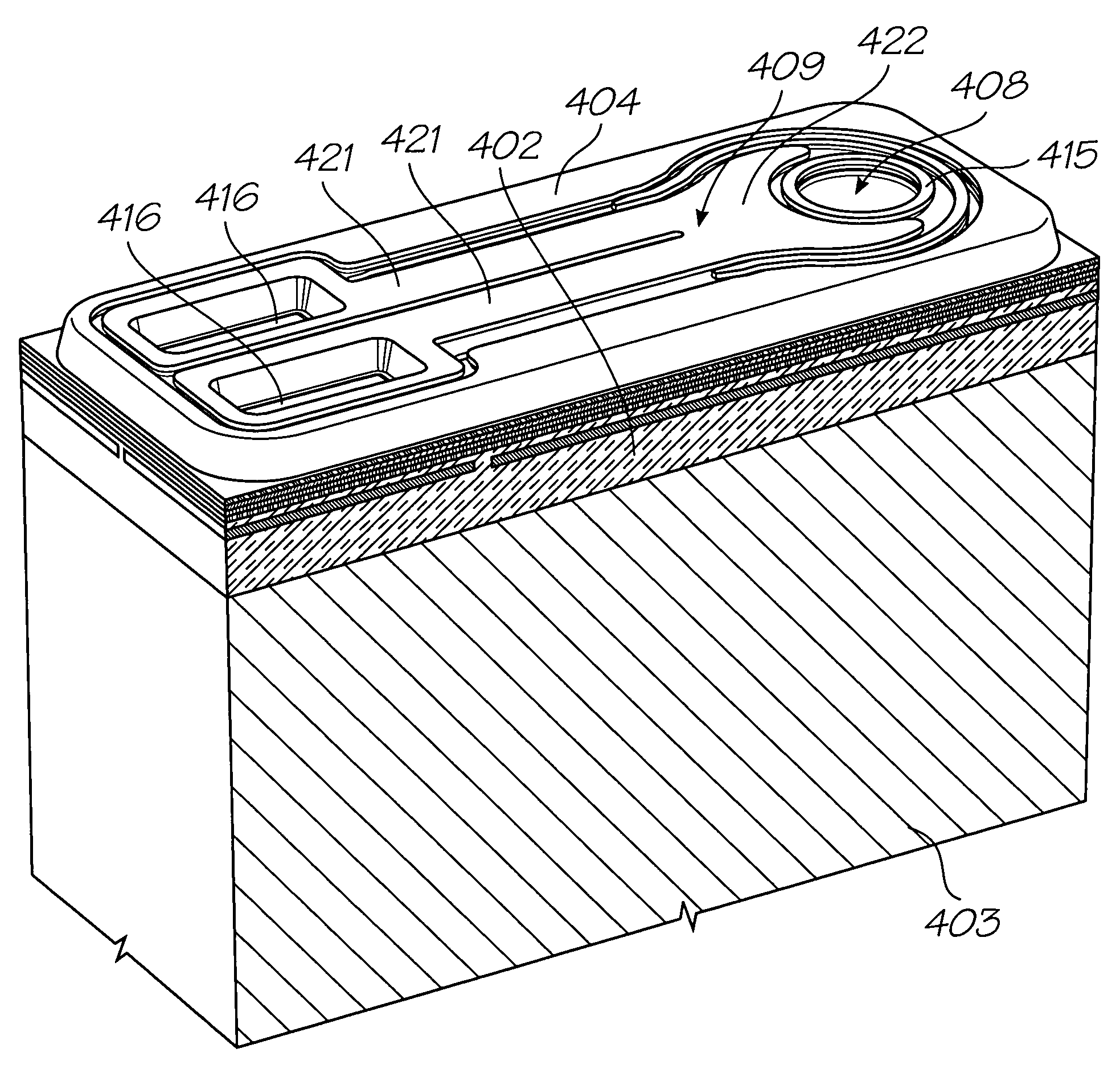
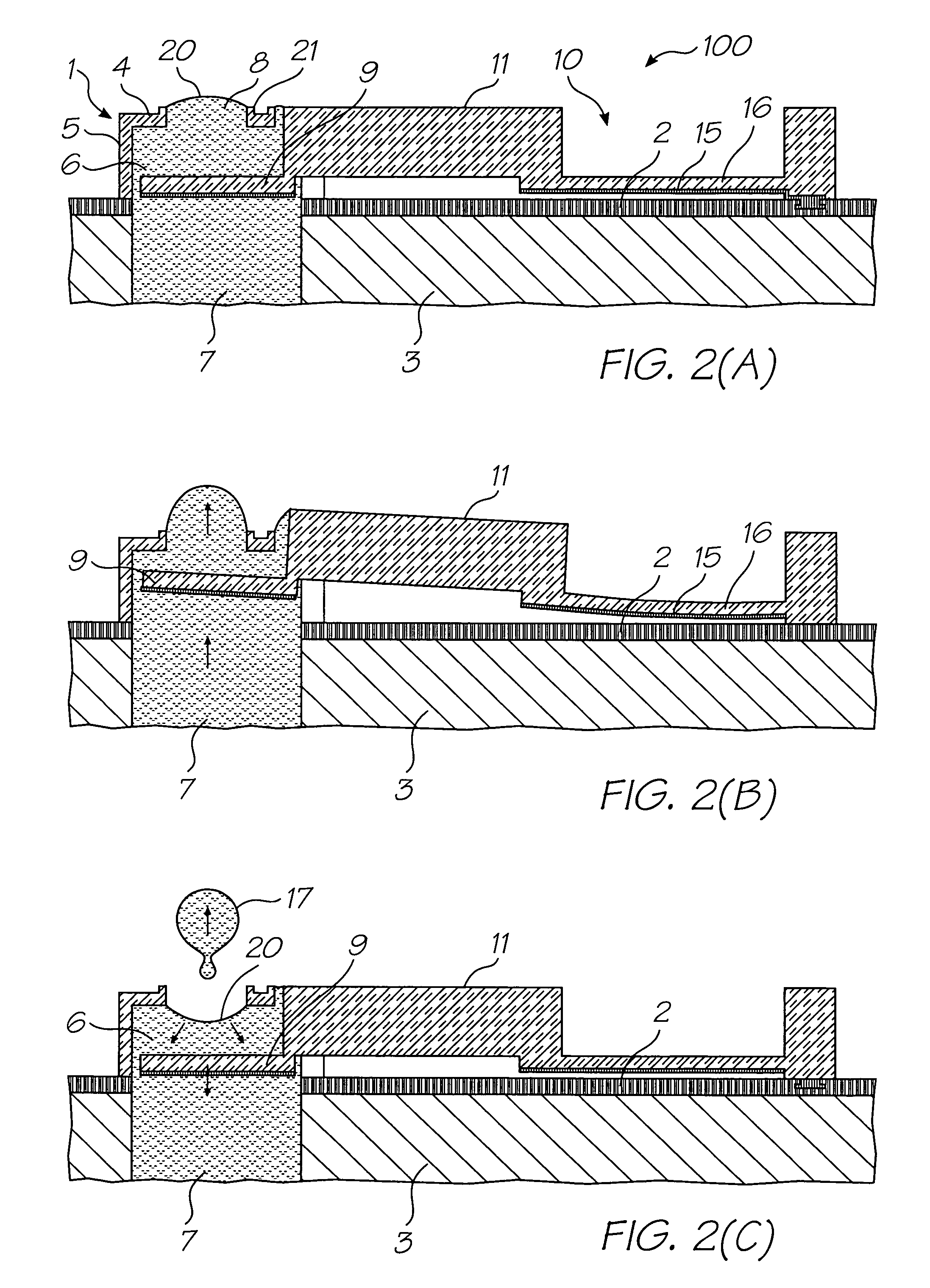
[0195]Turning initially to FIGS. 2(A) and 3, there are shown schematic illustrations of a nozzle assembly 100 according to a The nozzle assembly 100 is formed by MEMS processes on a passivation layer 2 of a silicon substrate 3, as described in U.S. Pat. No. 6,416,167. The nozzle assembly 100 comprises a nozzle chamber 1 having a roof 4 and sidewall 5. The nozzle chamber 1 is filled with ink 6 by means of an ink inlet channel 7 etched through the substrate 3. The nozzle chamber 1 further includes a nozzle opening 8 for ejection of ink from the nozzle chamber. An ink meniscus 20 is pinned across a rim 21 of the nozzle opening 8, as shown in FIG. 2(A).

[0196]The nozzle assembly 100 further comprises a paddle 9, positioned inside the nozzle chamber 1, which is interconnected via an arm 11 to an actuator 10 positioned externally of the nozzle chamber. As shown more clearly in FIG. 2, the arm extends through a slot 12 in nozzle chamber 1. Surface tension of ink within the slot 12 is suffi...

second embodiment

[0205]Turning now to FIGS. 5 to 8, there is shown a nozzle assembly 300, in accordance with a Referring to FIGS. 5 to 7 of the accompanying drawings, the nozzle assembly 300 is constructed (by way of MEMS technology) on a substrate 301 defining an ink supply aperture 302 opening through a hexagonal inlet 303 (which could be of any other suitable configuration) into a chamber 304. The chamber is defined by a floor portion 305, roof portion 306 and peripheral sidewalls 307 and 308 which overlap in a telescopic manner. The sidewalls 307, depending downwardly from roof portion 306, are sized to be able to move upwardly and downwardly within sidewalls 308 which depend upwardly from floor portion 305.

[0206]The ejection nozzle is formed by rim 309 located in the roof portion 306 so as to define an opening for the ejection of ink from the nozzle chamber as will be described further below.

[0207]The roof portion 306 and downwardly depending sidewalls 307 are supported by a bend actuator 310 ...


PUM


Abstract

An inkjet nozzle assembly is provided. The assembly comprises a nozzle chamber comprising a floor and a roof. The roof has a nozzle opening defined therein, and a moving portion moveable towards the floor. The assembly further comprises a thermal bend actuator, having a plurality of cantilever beams, for ejecting ink through the nozzle opening. A first active beam of the actuator defines at least part of an exterior surface of the roof.

Description

FIELD OF THE INVENTION[0001]This invention relates to thermal bend actuators. It has been developed primarily to provide improved inkjet nozzles which eject ink via thermal bend actuation.CO-PENDING APPLICATIONS[0002]The following applications have been filed by the Applicant simultaneously with the present application:[0003]11 / 607,97611 / 607,97511 / 607,99911 / 607,98011 / 607,97811 / 563,684[0004]The disclosures of these co-pending applications are incorporated herein by reference.CROSS REFERENCE[0005]The following patents or patent applications filed by the applicant or assignee of the present invention are hereby incorporated by cross-reference.[0006]6,988,8416,641,3156,786,6616,808,3256,750,9016,476,8636,788,3366,712,4536,460,9716,428,1476,416,1706,402,3006,464,3406,612,6876,412,9126,447,0997,249,1086,566,8586,331,9466,246,9706,442,5257,346,58609 / 505,9516,374,3547,246,0986,816,9686,757,8326,334,1906,745,3317,249,1097,197,6427,093,1397,509,29210 / 636,28310 / 866,6087,210,0387,401,22310 / 940,...

Claims


Application Information

Patent Timeline
Patent Type & Authority Patents(United States)
IPC IPC(8): B41J2/04
CPCB41J2/14427B41J2202/03B41J2002/14435
Inventor MCAVOY, GREGORY JOHNSILVERBROOK, KIA
Owner MEMJET TECH LTD
Why Eureka
Try Eureka