Heavy duty toggle bolt fastener for accommodating long screws and having properly positioned toggle nut component

a toggle bolt and long screw technology, applied in the direction of fastening means, dowels, mechanical equipment, etc., can solve the problems of inability to fixly secure the length or longitudinal extent of the threaded screw or bolt fastener that may be employed within any one of such toggle-bolt type fasteners is necessarily limited, and the operation of the toggle-bolt type fastener does not exhibit any operational deficiencies

Active Publication Date: 2009-11-03
ILLINOIS TOOL WORKS INC
View PDF23 Cites 75 Cited by
  • Summary
  • Abstract
  • Description
  • Claims
  • Application Information

AI Technical Summary

Benefits of technology

[0006]The foregoing and other objectives are achieved in accordance with the teachings and principles of the present invention through the provision of a new and improved toggle-bolt type fastener which comprises a fastener body portion having a substantially cylindrically tubular cross-sectional configuration. A first pair of slots are provided within first, diametrically opposed side wall regions of the fastener body portion so as to permit pin members or trunnions of a pivotal nut member to slidably move therewithin, and a second pair of slots are provided within second, diametrically opposed side wall regions of the fastener body portion so as to permit the nut member to move from its first or original, axially oriented, inoperative or non-deployed position to its second, transversely oriented, operative or deployed position. A cross-brace member extends across one of the side wall portions of the fastener body portion, at a position immediately forwardly of the first pair of slots defined within the fastener body portion, and effectively spans one of the second slots, through which a portion of the nut member passes as the nut member moves from its first or original, axially oriented, inoperative or non-deployed position to its second, transversely oriented, operative or deployed position, such that the nut member will engage the cross-brace member when the nut member effectively attains its second, transversely oriented, operative or deployed position. In this manner, the cross-brace member effectively ensures the fact that the nut member is properly disposed at its transversely oriented, operative or deployed position which is substantially perpendicular to the longitudinal axis of the toggle-bolt type fastener such that proper threaded engagement of the nut member, by means of the threaded screw or bolt fastener, is effectively ensured.
[0007]Still further, the self-drilling tip portion of the toggle-bolt type fastener includes an arcuately curved portion which extends inwardly from the outer periphery of the toggle-bolt type fastener toward the longitudinal axis thereof, along which the actual self-drilling stab point is located, such that when an extra-long threaded screw or bolt fastener begins to engage the self-drilling tip portion of the toggle-bolt type fastener, the forward end tip portion of the threaded screw or bolt-type fastener will effectively be guided, by means of the arcuate curvature characteristic of the self-drilling tip portion, into engagement with the self-drilling stab point whereby the threaded screw or bolt fastener can be slightly deflected from its coaxial disposition with respect to the toggle-bolt type fastener and thereby effectively bypass the self-drilling stab point of the toggle-bolt type fastener. In this manner, the toggle-bolt type fastener can in fact accommodate extra-long threaded screws or bolt fasteners whereby a single threaded screw or bolt fastener can be utilized regardless of the thickness dimensions of the various articles or objects being mounted upon the drywall structure. It is also noted that the slight deflection of the threaded screw or bolt fastener from its coaxial disposition with respect to the toggle-bolt type fastener does not adversely affect the threaded engagement defined between the threaded screw or bolt fastener and the nut member of the toggle-bolt type fastener in view of the fact that, at this point in time, the threaded screw or bolt fastener has already been properly threadedly engaged with the nut member. Still yet further, alternative structure may likewise be incorporated within the body portion of the toggle-bolt type fastener, just immediately rearwardly of the self-drilling pointed tip, so as not to necessarily cause the aforenoted slight deflection of the threaded screw or bolt fastener but, to the contrary, simply permit the tip portion of the extra-long threaded screw or bolt fastener to be simply parked or accommodated.

Problems solved by technology

While the aforenoted types of toggle-bolt type fasteners have of course been generally satisfactory from an overall operational point of view, such fasteners do in fact exhibit some operational deficiencies.
Accordingly, the length or longitudinal extent of the threaded screw or bolt fastener that may be employed within any one of such toggle-bolt type fasteners is necessarily limited in that the tip portion of the threaded screw or bolt fastener cannot be permitted to engage the self-drilling tip portion because the threaded screw or bolt fastener would then effectively be prevented from being fully disposed within the toggle-bolt type fastener whereby it would not be possible to fixedly secure the toggle-bolt type fastener, as well as the particular object or article, upon the drywall structure.
Accordingly, when the threaded screw or bolt fastener is fully threadedly inserted or installed so as to securely mount the particular object or article upon the drywall structure, the toggle member will not properly or securely engage the rear or inner side or surface portion of the drywall structure whereby, in turn, the particular object or article will not be securely mounted upon the drywall structure.

Method used


Image

  • Heavy duty toggle bolt fastener for accommodating long screws and having properly positioned toggle nut component
  • Heavy duty toggle bolt fastener for accommodating long screws and having properly positioned toggle nut component
  • Heavy duty toggle bolt fastener for accommodating long screws and having properly positioned toggle nut component

Examples


first embodiment

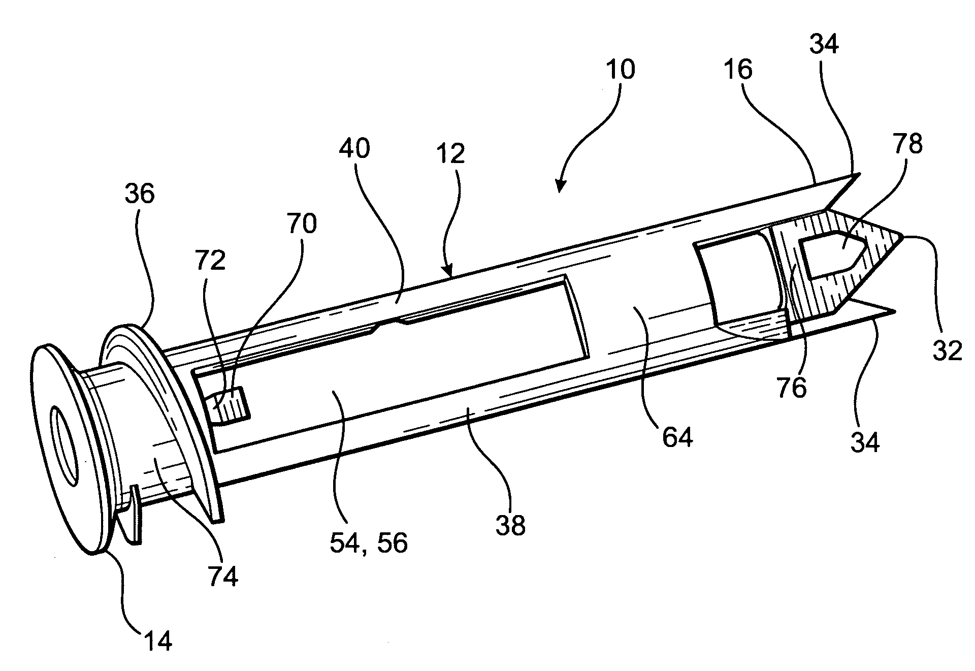
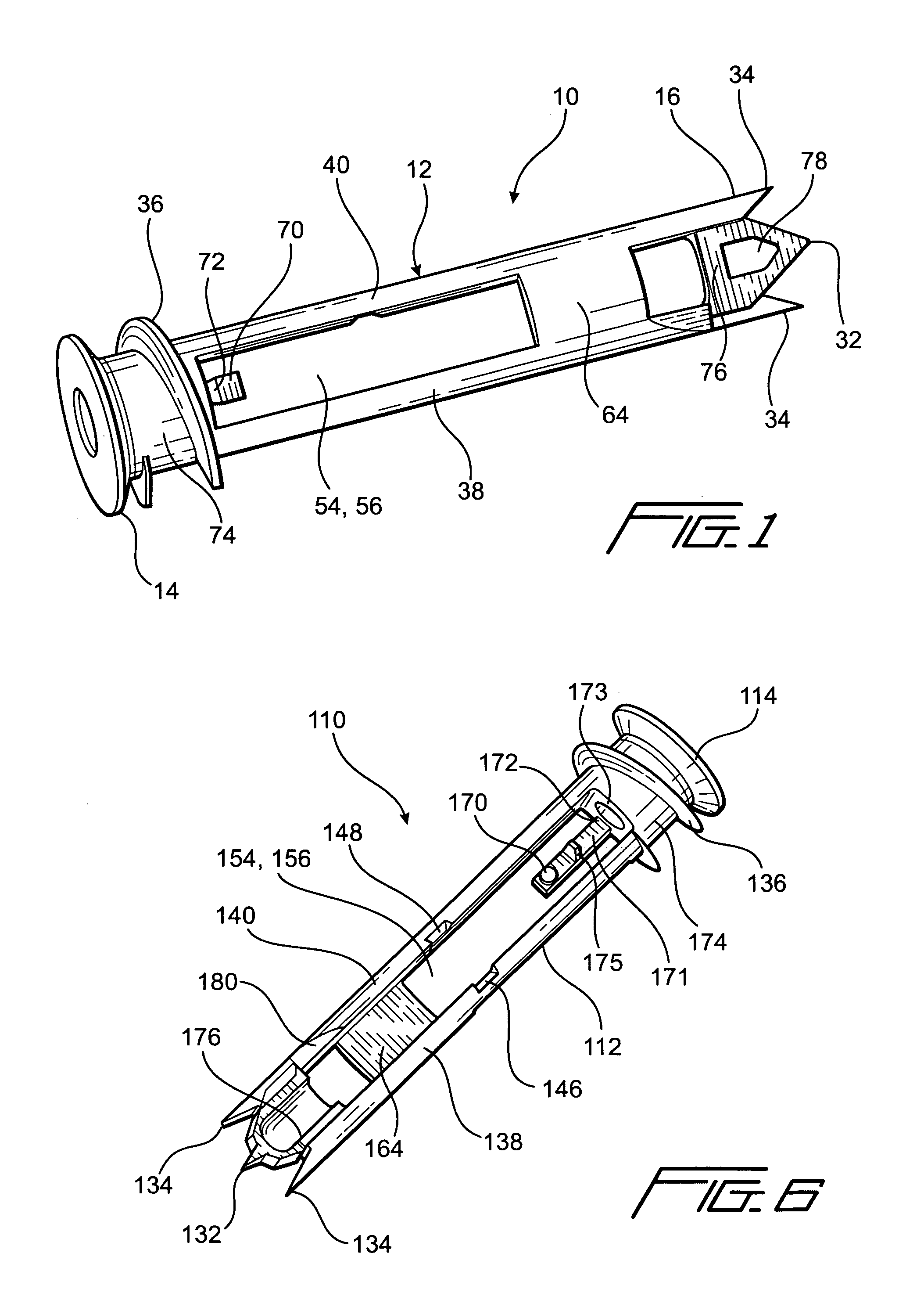
[0023]Referring now to the drawings, and more particularly to FIGS. 1-4 thereof, a new and improved toggle-bolt type fastener, constructed in accordance with the principles and teachings of the present invention and showing the various cooperative parts thereof for achieving the operational objectives of the present invention, is disclosed and is generally indicated by the reference character 10. More particularly, it is seen that the new and improved toggle-bolt type fastener 10 is seen to comprise a body portion 12, a head portion 14 integrally connected to one end of the body portion 12, and a self-drilling tip portion 16 integrally connected to an opposite end of the body portion 12. The body portion 12 has a substantially cylindrically tubular cross-sectional configuration, and it is noted that the thickness of the peripheral wall member of the body portion 12 is approximately 0.072 inches, which effectively imparts a sufficient degree of reinforcement to the peripheral wall me...

second embodiment

[0035]With reference now being made to FIGS. 6 and 7, a new and improved toggle-bolt type fastener, constructed in accordance with the teachings and principles of the present invention and showing the various cooperative parts thereof for likewise achieving the operational objectives of the present invention comprising the proper disposition of the nut member and the accommodation of extra-long threaded screws or bolt fasteners, is disclosed and is generally indicated by the reference character 110. It is firstly noted that in the interest of brevity, those structural components of the toggle-bolt type fastener 110, which correspond or are similar to those structural components of the toggle-bolt type fastener 10, will not be discussed in detail, but to the contrary, the discussion of the toggle-bolt type fastener 110 will be limited to the structural differences that exist between the toggle-bolt type fastener 110 and the toggle-bolt type fastener 10, and secondly, those structural...

third embodiment

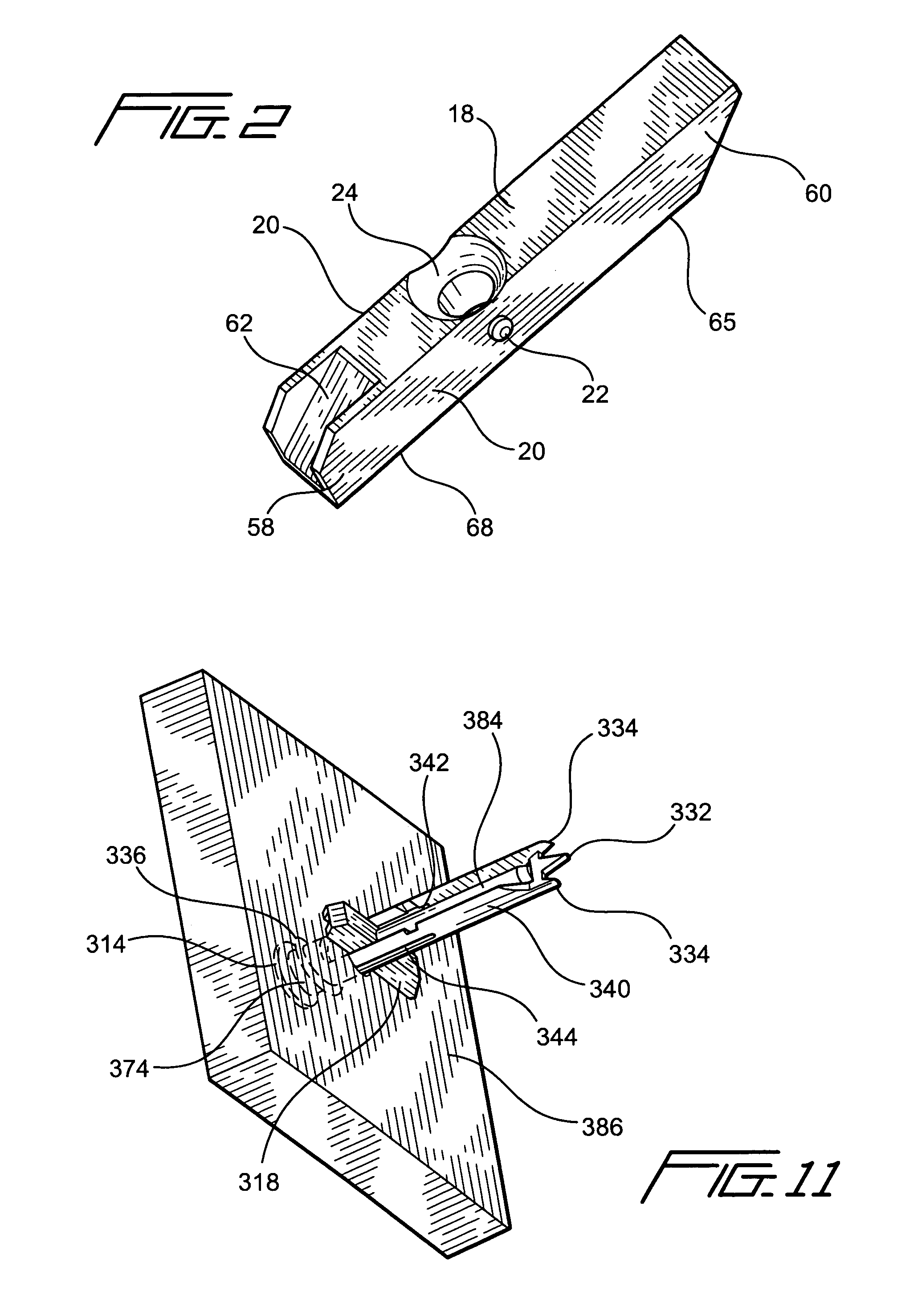
[0037]With reference now being made to FIG. 8, a new and improved toggle-bolt type fastener, constructed in accordance with the teachings and principles of the present invention and showing the various cooperative parts thereof for likewise achieving the operational objectives of the present invention comprising the proper disposition of the nut member and the accommodation of extra-long threaded screws or bolt fasteners, is disclosed and is generally indicated by the reference character 210. It is again noted that in the interest of brevity, those structural components of the toggle-bolt type fastener 210, which correspond or are similar to those structural components of the toggle-bolt type fasteners 10,110 will not be discussed in detail, but to the contrary, the discussion of the toggle-bolt type fastener 210 will be limited to the structural differences that exist between the toggle-bolt type fasteners 10,110 and the toggle-bolt type fastener 210, the structural components of t...


PUM


Abstract

A toggle-bolt type fastener has pocket structure incorporated therein for accommodating extra-long threaded bolt fasteners in a coaxial manner within the toggle-bolt type fastener. Alternatively, structure has been incorporated within the toggle-bolt type fastener which accommodates extra-long threaded bolt fasteners by causing the same to be slightly deflected from their coaxial disposition within the toggle-bolt type fastener so as to permit the same to bypass the pointed tip of the toggle-bolt type fastener. Still further, additional structure has been incorporated within the toggle-bolt type fastener for ensuring the fact that when the nut member is moved from its original, axially oriented, inoperative or non-deployed position, to its second, transversely oriented, operative or deployed position, the nut member will in fact be disposed substantially perpendicular to the longitudinal axis of the toggle-bolt type fastener so as to ensure the proper threaded engagement thereby by the threaded bolt fastener.

Description

FIELD OF THE INVENTION[0001]The present invention relates generally to toggle-bolt fastener assemblies for mounting various objects or articles, such as, for example, pictures, mirrors, shelving, lighting fixtures, brackets, and the like, upon drywall or support panel structures, and more particularly to a new and improved toggle-bolt fastener assembly which comprises structure for enabling the accommodation of extra-long screws and which effectively ensures the proper deployment of the toggle nut component from its coaxially aligned inoperative stored position to its perpendicular operative drywall-engaging position.BACKGROUND OF THE INVENTION[0002]Various toggle-bolt type fasteners have of course been developed within the past several decades, and are of course well-known in the building industry, wherein the toggle-bolt type fasteners have been specifically adapted for use in connection with the mounting of various objects or articles, such as, for example, pictures, mirrors, she...

Claims


Application Information

Patent Timeline
Patent Type & Authority Patents(United States)
IPC IPC(8): F16B21/00
CPCF16B13/0808F16B13/002
Inventor PANASIK, CHERYL L.MANSOUR, NAIMERNST, RICHARD J.
Owner ILLINOIS TOOL WORKS INC
Why Eureka
Try Eureka