Positioning bridge guide and its utilisation for the nozzle support pipe of a turboprop

a technology of nozzle support pipe and positioning bridge, which is applied in the direction of sustainable transportation, mechanical equipment, machines/engines, etc., can solve the problems of lack of flexibility, deformation transmission to the nozzle support pipe and the heat shield liner, and the association with this lack of flexibility

Active Publication Date: 2009-11-10
SN DETUDE & DE CONSTR DE MOTEURS DAVIATION S N E C M A
View PDF17 Cites 11 Cited by
  • Summary
  • Abstract
  • Description
  • Claims
  • Application Information

AI Technical Summary

Problems solved by technology

The main inconvenience of this solution is the lack of flexibility.
The risks associated with this lack of flexibility are, amongst other things, the fact that the deformation may be transmitted to the nozzle support pipe and the heat shield liner.
But these parts are complex, expensive and, if damaged, are liable to cause malfunctions of the turboprop.
In particular, there is the possibility of implosion of the heat shield liner bringing about partial obstruction of the engine main exhaust flow, local dishing of the nozzle support pipe with associated ruptures.
On the other hand, the thermal gradient between the diaphragm upstream and downstream is not satisfactory for the engine structure.
In fact, thermal fatigue has been noted, provoking longitudinal and then circumferential edge cracks leading up to loss of sector portions.

Method used


Image

  • Positioning bridge guide and its utilisation for the nozzle support pipe of a turboprop
  • Positioning bridge guide and its utilisation for the nozzle support pipe of a turboprop
  • Positioning bridge guide and its utilisation for the nozzle support pipe of a turboprop

Examples


Embodiment Construction

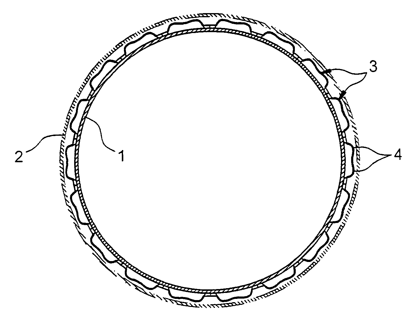
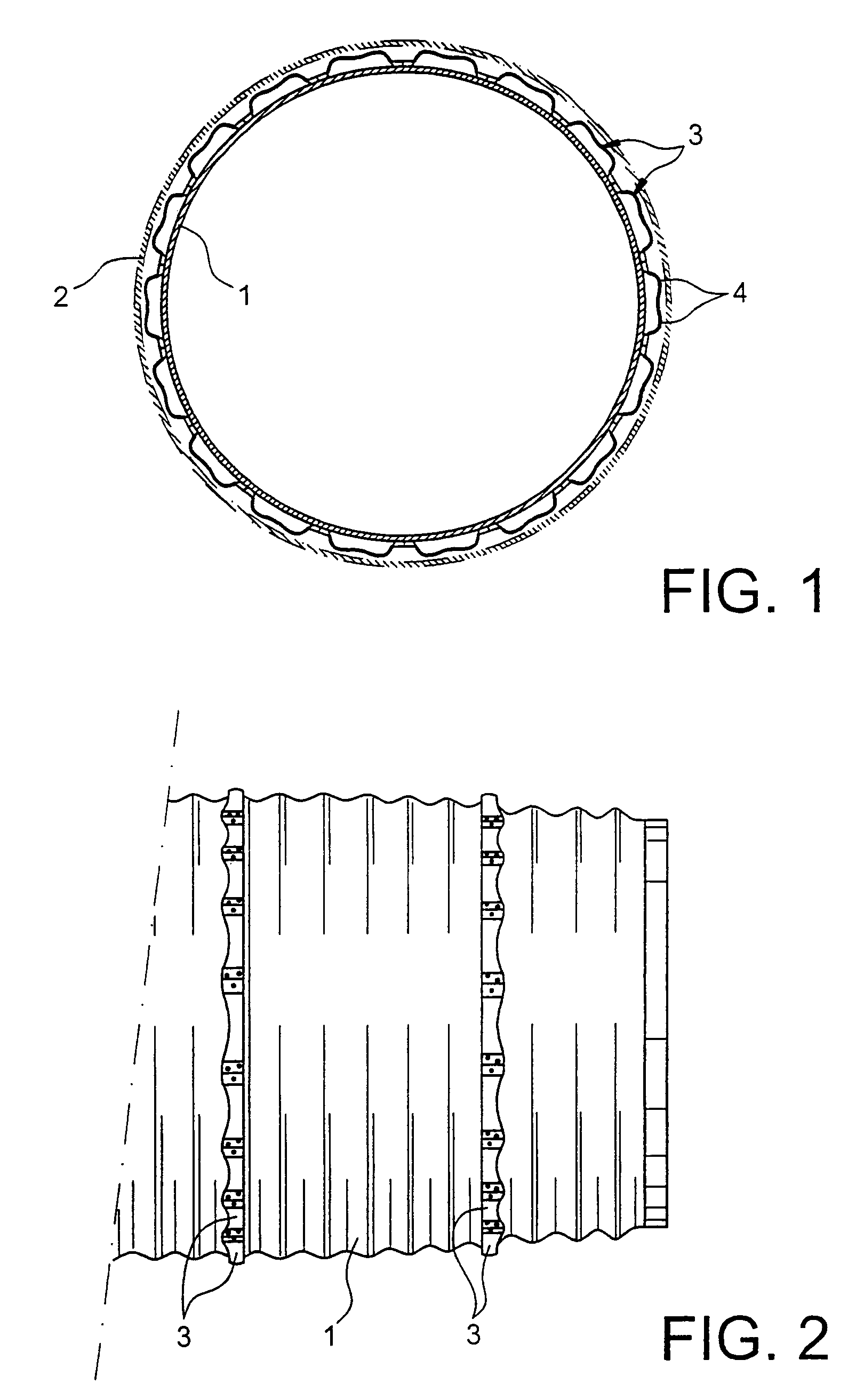
[0021]FIG. 1 shows the circumferential settings of bridge pieces 3 according to the invention, on a heat shield liner 1 of a turboprop nozzle. The two thin broken lines 2 represent the outer positions of the nozzle support pipe envelope. It can be seen that the space between the heat shield liner 1 and the cooling air bypass flow pipe envelope 2 is of the order of 10 mm. Consequently, the bridge pieces 3 are relatively flat. On the other hand, they must be able to support crushing of the order of 15 to 25% in height, while still ensuring sufficient mechanical hold.

[0022]FIG. 2 shows the longitudinal positioning of bridge pieces on the heat shield liner 1 of a turboprop nozzle. Thus it is possible and simple to produce several bridge piece 3 rows or rings over the whole length of this part in order to ensure the positioning of the cooling air bypass pipe envelope along its entire length.

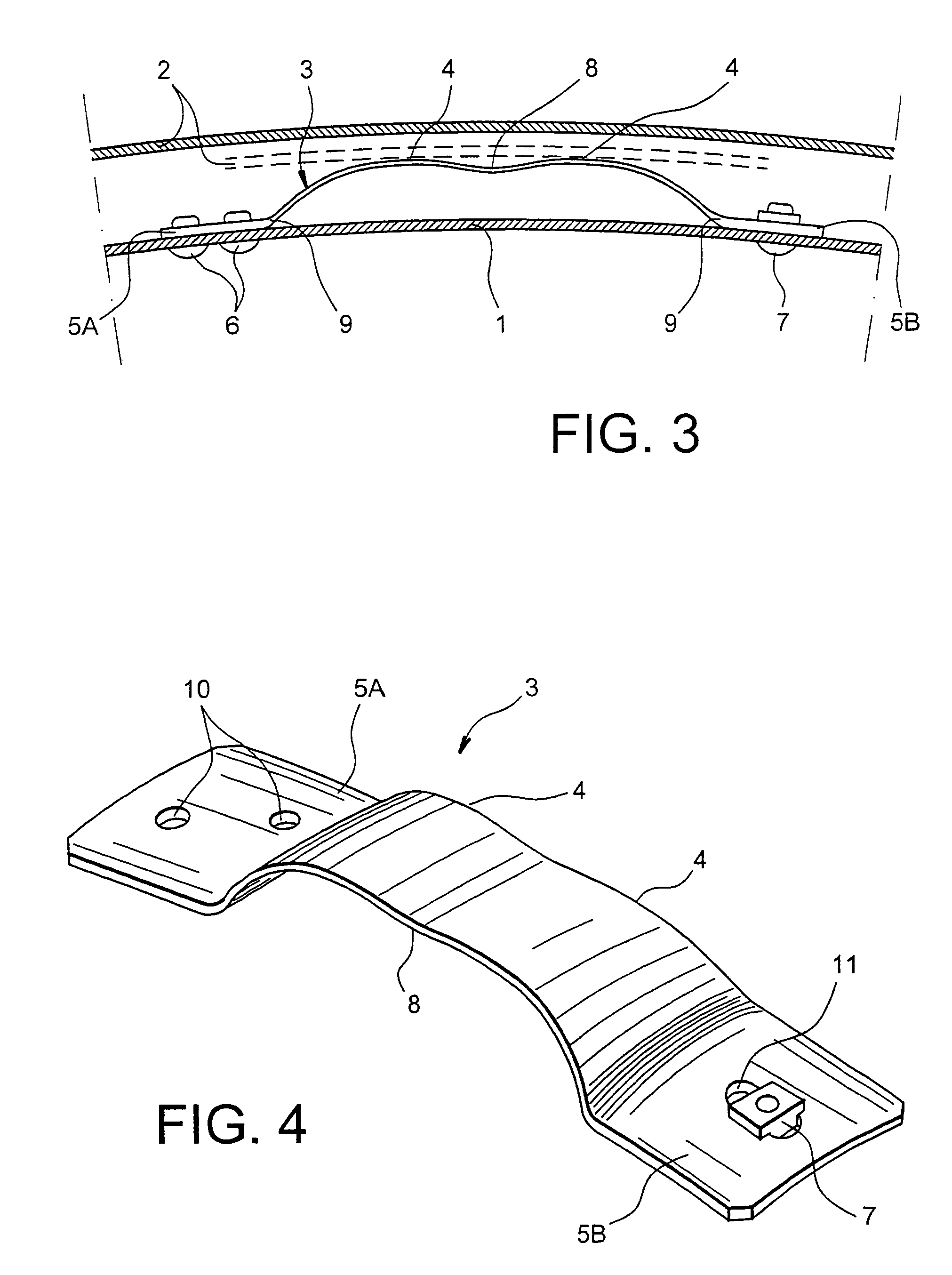
[0023]FIG. 3 shows in more detail the shape of the bridge pieces 3, especially their cambered cent...


PUM


Abstract

A bridge positioned between two parts, such as a nozzle support pipe envelope and a heat shield liner, includes a central part with inversed curvature thus having two contact zones with the nozzle support pipe envelope. Furthermore, the bridge includes two lugs, one of which can be mounted to slide in the heat shield liner.

Description

FIELD OF THE INVENTION[0001]The invention relates to the field of turboprops used in aeronautics, and more precisely the relative positioning of the heat shield liner and the nozzle support pipe for a thrusters, in particular a thrusters with cooling bypass air flow.PRIOR ART AND THE PROBLEM POSED[0002]In military type turboprops, using cooling bypass air flow, it is necessary to be able to constantly position the heat shield liner at the level of the nozzle relative to the nozzle support pipe. In other words, this involves centering the heat shield liner. In order to achieve this, bridge guides are used, spaced around the whole circumference of the internal envelope, that is the heat shield liner. Reference can be made to figure 1 without taking into account the shape of the bridge guides 3 placed between the heat shield liner 1 and the nozzle support pipe envelope 2. Furthermore, these bridge guides must also fulfill a diaphragm function relative to the bypass air flow circulating...

Claims


Application Information

Patent Timeline
Patent Type & Authority Patents(United States)
IPC IPC(8): F02K3/10F02C7/00F01D25/24F01D25/26F02C7/20F02K1/78F02K1/82
CPCF01D25/24F02C7/20F02K1/822F05D2230/642Y02T50/675Y02T50/60
Inventor MANDET, EMMANUEL CHRISTOPHEROCHE, JACQUES-ASALPERWYCK, LAURENT CLAUDE PATRICK
Owner SN DETUDE & DE CONSTR DE MOTEURS DAVIATION S N E C M A
Why Eureka
Try Eureka