Electrical-wire-protecting member

A technology for protecting components and wires, applied to electrical components, parts of connecting devices, circuits, etc., can solve the problems of not properly fixing the second bellows 521, short contact parts, etc.

Active Publication Date: 2015-04-01
YAZAKI CORP
View PDF7 Cites 7 Cited by
  • Summary
  • Abstract
  • Description
  • Claims
  • Application Information

AI Technical Summary

Problems solved by technology

Therefore, if the second bellows 521 is fixed by wrapping the cable tie 513 around the entire outer circumference of the pipe insertion portion 505 in the same manne...

Method used


Image

  • Electrical-wire-protecting member
  • Electrical-wire-protecting member
  • Electrical-wire-protecting member

Examples


Embodiment Construction

[0063] Embodiments of the present invention will be described below with reference to the drawings.

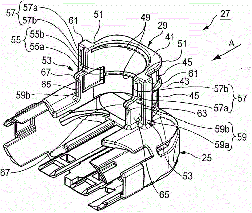
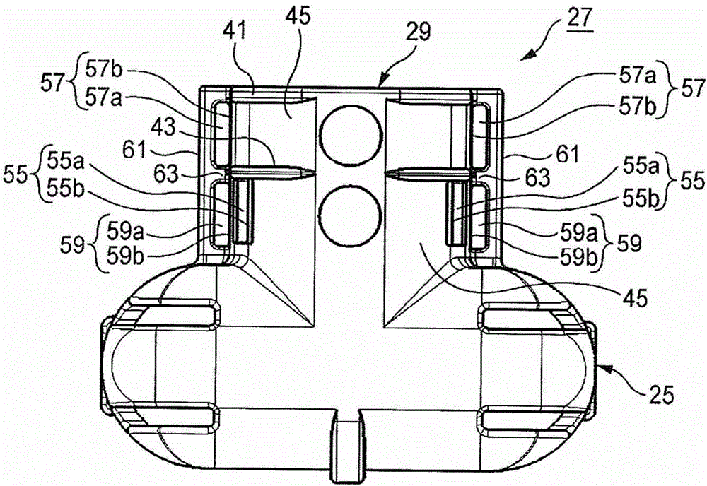
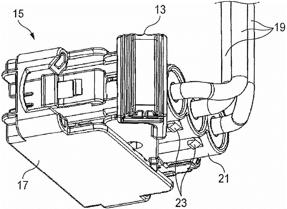
[0064] The wire protection member according to the embodiment of the present invention is used as a wire cover, a wire harness protector, and the like. This embodiment illustrates an example of a wire protection member as the wire cover 11 . The wire cover 11 can be applied to, for example, a small insertion force connector 15 (see Figure 2A and 2B ), the low insertion force connector 15 is a connector having a lever 13 for reducing the force required to insert into a mating connector (not shown).

[0065] Such as Figure 2A and 2B As shown, in the low insertion force connector 15 , a plurality of terminals (not shown) are accommodated in the connector housing 17 . The electric wires 19 are connected to the respective terminals, and are led out from the housing rear portion 21 on the opposite side from the side fitted into or with the mating connector. A housing rear po...


PUM


Abstract

This electrical-wire cover is provided with the following: a corrugated-tube affixing part (29) and engagement ridges (49) integrally formed on a cover body (27) that surrounds an electrical wire; a bundling band that tightly secures first through third corrugated tubes; and bundling-member confinement parts (53) provided on the corrugated-tube affixing part (29). Each bundling-member confinement part (53) has first through third positioning parts (55, 57, 59) that have different bundling-band bridging positions.

Description

technical field [0001] The present invention relates to an electric wire protection component. Background technique [0002] Among known connectors equipped with a cover for fixing a bellows to a connector housing, there are connectors that enable appropriate fixing of bellows having different outer diameters (for example, see Patent Document 1). [0003] This type of connector is configured such that a connector housing and a connector cover (wire protection member) which are separate components can be separated from each other. Such as Figure 7A and 7B As shown, the connector cover 501 is provided with a fitting portion 503 and a tube insertion portion 505 . The fitting portion 503 is locked on a locking portion (not shown) of the connector housing, and thereby fitted in or with the connector housing. The tube insertion portion 505 is provided with a cable tie restricting portion 507 that determines a binding position of a cable tie (binding member) 513 by a first rest...

Claims


Application Information

Patent Timeline
IPC IPC(8): H02G3/04H01R13/52H01R13/56H02G3/30
CPCH01R13/56H02G3/0468H02G3/088H01R13/5825H01R13/567H01R13/58H01B7/17
Inventor 铃木谦志梶川謙士
Owner YAZAKI CORP
Why Eureka
Try Eureka