
Rolling shutter for prevention of blooming

a technology of rolling shutter and shutter blade, which is applied in the direction of color television details, television system details, television systems, etc., can solve the problems of exacerbated blooming problems, insufficient shutter technique compensation, and distortion of images

Active Publication Date: 2009-11-17
MICRON TECH INC
View PDF2 Cites 17 Cited by
  • Summary
  • Abstract
  • Description
  • Claims
  • Application Information

AI Technical Summary

Benefits of technology

The present invention uses a rolling shutter technique with multiple hard reset rows to counteract the effects of blooning. The advantages of this technique include ensuring that each row is in a true hard reset condition at the beginning of the integration period and making it less likely that overexposed pixels several rows away will be able to distort the given row. The hard reset rows are arranged as non-consecutive rows and the number of rows in the array minus X (the number of rows needed to integrate the pixel result) is used as a reference for determining the number of hard reset rows.

Problems solved by technology

This is typically due to exposure of a pixel to an overly intense light source, or to exposing the pixel for too long a period of time.
This overflow distorts the image, and can wash out portions of the image near the overexposed portion.
This conventional rolling shutter technique does not adequately compensate for blooming, however.
This blooming problem is exacerbated when, as is often the case in overexposure situations, large groups of adjacent pixels are exposed to intense light and become overexposed.
Conventional rolling shutters cannot fully compensate for this phenomenon.
Also, because electrons can be deflected farther than the dimensions of an individual pixel, the hard resetting of row 17 will not prevent photon overflow to still integrating row 16.

Method used


Image

  • Rolling shutter for prevention of blooming
  • Rolling shutter for prevention of blooming
  • Rolling shutter for prevention of blooming

Examples


Embodiment Construction

[0029]Referring now to FIGS. 3A-3D, a portion of a CMOS pixel array 140 is shown. The array 140, overexposed pixel 210 and bloom region 211 have the same designations as discussed above with respect to FIGS. 2A-2F. A rolling shutter according to present invention, controlled by control circuit 150 (FIG. 1B) and having read row 300 and hard reset rows 301-305 (Y=5), is also shown. The integration time X of the rolling shutter is 10 rows, as in FIGS. 2A-2F. Thus, as each row 300 is sequentially read (designated as row N), rows 301-305 will simultaneously be hard reset (designated as rows N+X through N+X+(Y−1)).

[0030]Thus, referring now to FIG. 3A, as row 5 is the read row 300, rows 15-19 are hard reset. By hard resetting multiple rows, a much more significant portion of the bloom region 211 is hard reset before integration, thereby making it more difficult for the overexposed pixel to deflect or overflow electrons into rows that are still being integrated and being, or about to be rea...


PUM


Abstract

A rolling shutter technique for a pixel array is described in which multiple rows of the array are hard reset as the shutter moves down the array. As the rolling shutter progresses down the array, each row is hard reset multiple times before its integration period begins, thereby ensuring that the row is in a true hard reset condition at the beginning of its integration period. Also, multiple rows are hard reset in advance of the beginning of the integration period for a given row, thereby making it less likely that overexposed pixels several rows away will be able to distort the integrating row by blooming.

Description

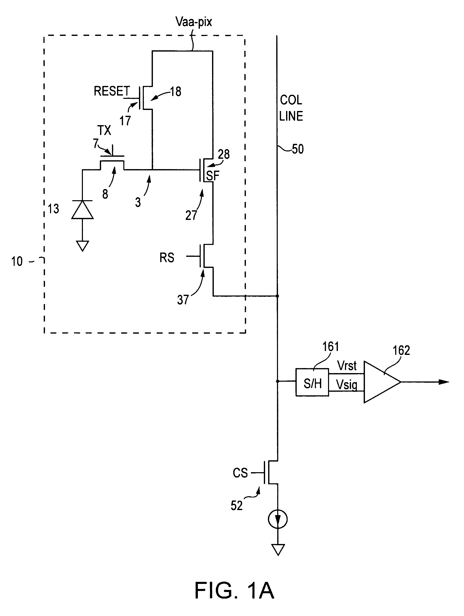
FIELD OF THE INVENTION[0001]The present invention relates to a rolling shutter for the prevention of blooming in a CMOS pixel cell array.BACKGROUND OF THE INVENTION[0002]Image sensors are used in a variety of digital image capture systems, including products such as scanners, copiers, and digital cameras. The image sensor is typically composed of an array of light-sensitive pixel cells that are electrically responsive to incident light reflected from an object or scene whose image is to be captured.[0003]A CMOS imager includes a focal plane array of pixel cells, each cell includes a photosensor, for example, a photogate, photoconductor or a photodiode overlying a substrate for producing a photo-generated charge in a doped region of the substrate. In a CMOS imager, the active elements of a pixel cell, for example a four transistor (4T) pixel cell, perform the necessary functions of (1) photon to charge conversion; (2) resetting a floating diffusion region to a known state; (3) transf...

Claims


Application Information

Patent Timeline
Patent Type & Authority Patents(United States)
IPC IPC(8): H04N3/14H04N5/353H04N5/359H04N5/374
CPCH04N5/3591H04N5/3532H04N25/531H04N25/621
Inventor SHAH, JOEY
Owner MICRON TECH INC
Learn More