
Method for Splicing Stress Skins used for Manufacturing Structural Insulated Panels

a technology of structural insulation and stress skins, which is applied in the direction of layered products, chemistry apparatus and processes, and other domestic articles, etc., can solve the problems of reducing the thermal efficiency of the sip, the length of the sips is limited by the available length of the skin material, and the method is less than desirabl

Active Publication Date: 2015-08-27
GILLMAN JERRY
View PDF6 Cites 8 Cited by
  • Summary
  • Abstract
  • Description
  • Claims
  • Application Information

AI Technical Summary

Benefits of technology

The present invention provides a method for manufacturing structural insulated panels with splicing stress skins through lamination, which allows for the production of longer panels without compromising thermal efficiency and structural integrity. The method involves using lower and upper sheets of serial panels, as well as splice plates, an insulating structure, and an insulating foam core. The resulting panels have a continuous stressed skin and are ideal for use in industrial structures such as apartments and houses. The method also includes a process for splicing multiple panels together without reducing the thermal efficiency or creating a structural hinge. Overall, the invention provides a more efficient and cost-effective way to manufacture structural insulated panels.

Problems solved by technology

As the structural integrity of the SIPs is based on a continuous stressed skin, lengths of SIPs have been limited by the available lengths of skin material.
This method is less than desirable as it forms a structural hinge at the splice point as well as a thermal break in the SIP.
The structural hinge creates a high stress region and the thermal break greatly reduces the thermal efficiency of the SIP both essential characteristics for industrial uses.

Method used


Image

  • Method for Splicing Stress Skins used for Manufacturing Structural Insulated Panels
  • Method for Splicing Stress Skins used for Manufacturing Structural Insulated Panels
  • Method for Splicing Stress Skins used for Manufacturing Structural Insulated Panels

Examples


Embodiment Construction

[0015]All illustrations of the drawings are for the purpose of describing selected versions of the present invention and are not intended to limit the scope of the present invention.

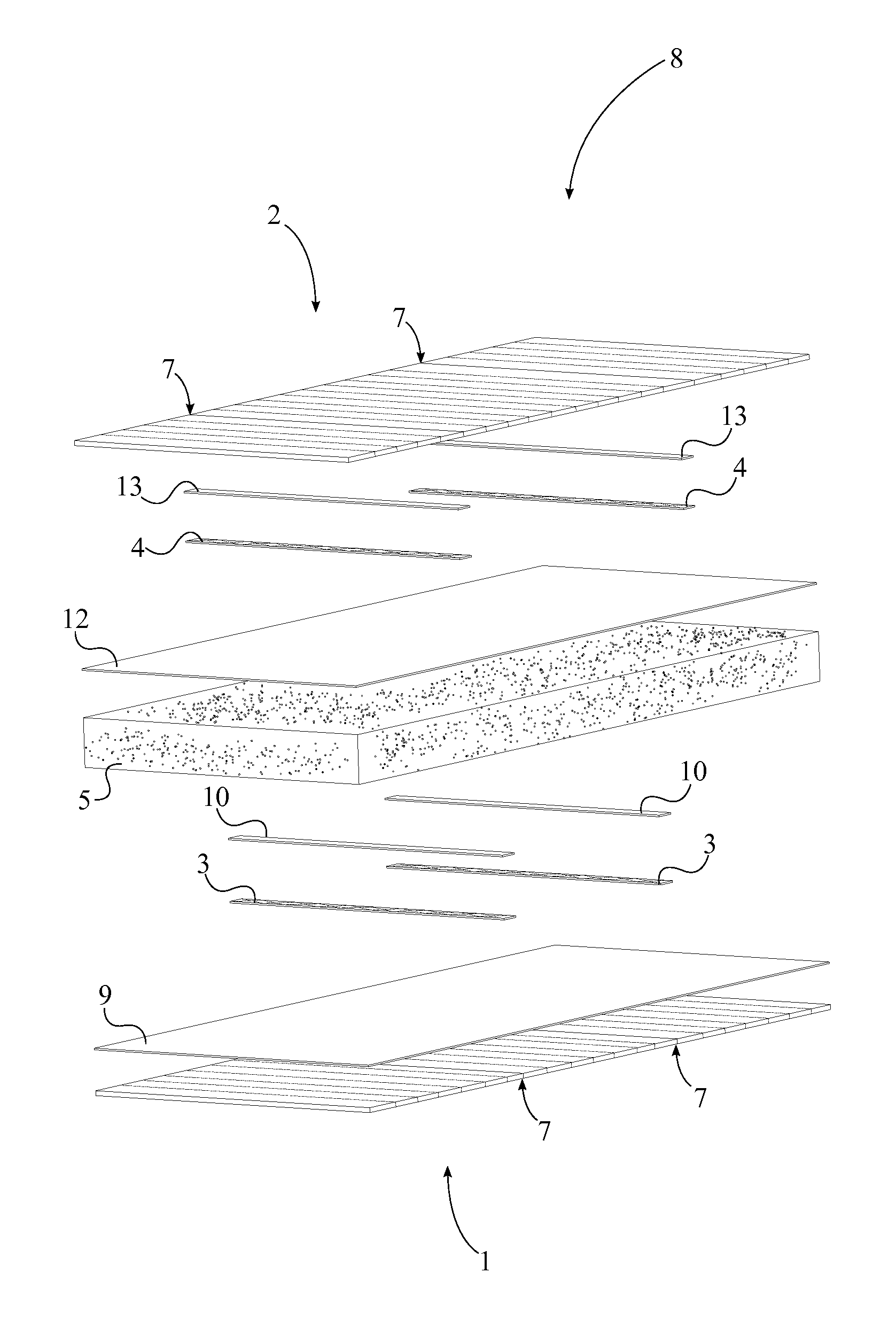
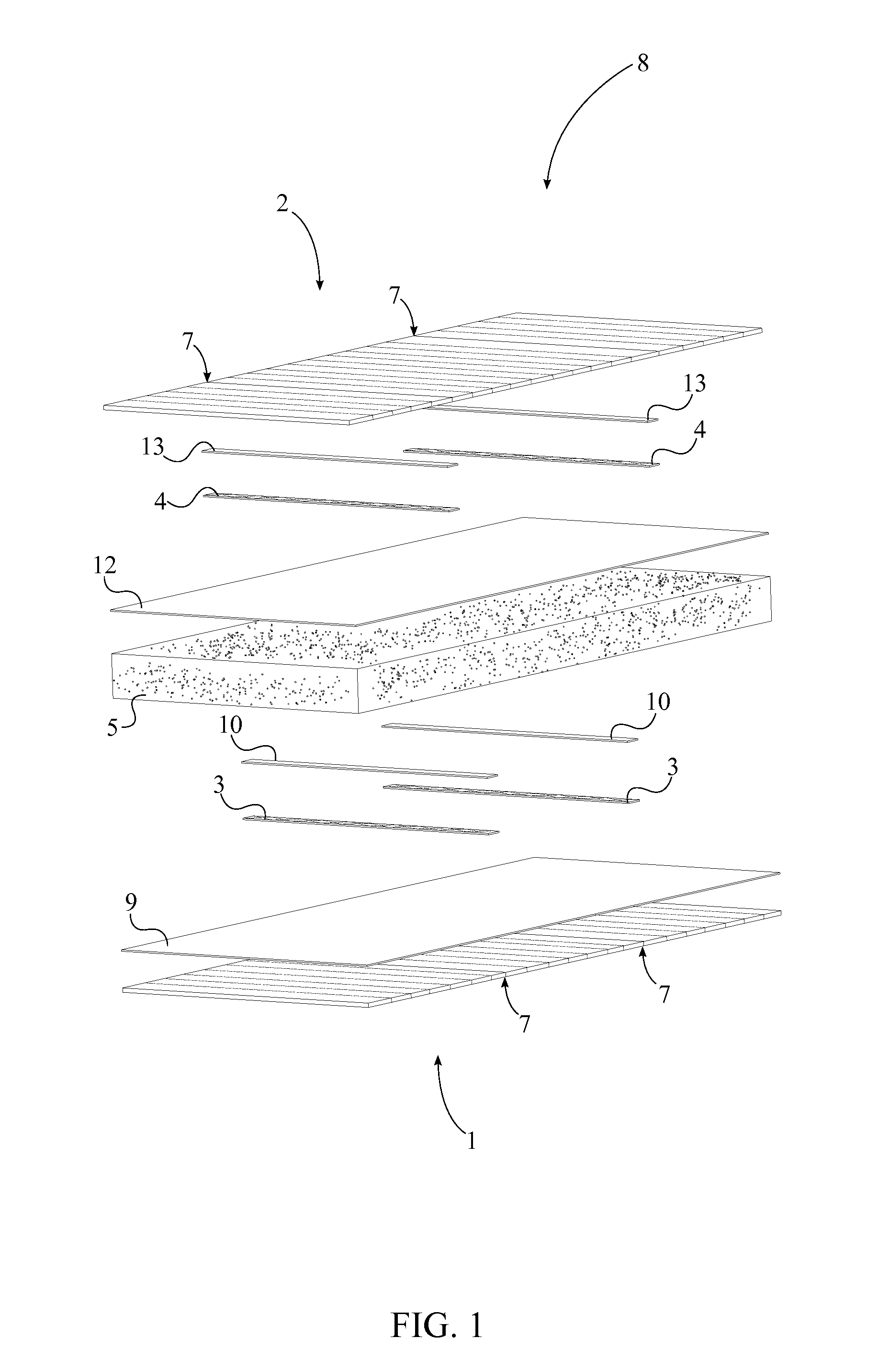
[0016]The present invention is the manufacturing method for structural insulated panels 8 with splicing stress skins through lamination. More specifically, the present invention is the manufacturing process which produces substantially longer structural insulated panels 8 compared to traditional means without sacrificing thermal efficiency and structural integrity. Traditional structural insulated panels 8 comprise a rigid insulating core sandwiched in between two layers of structural panels. Structural insulated panels 8 are ideal building material for constructing apartments, houses, and other similar structures. Due to the structural insulated panel's 8 high thermal efficiency less energy and effort is required to maintain adequate internal temperatures for houses and storage spaces which in turn decr...


PUM

PropertyMeasurementUnit
Lengthaaaaaaaaaa
Pressureaaaaaaaaaa
Widthaaaaaaaaaa

Abstract

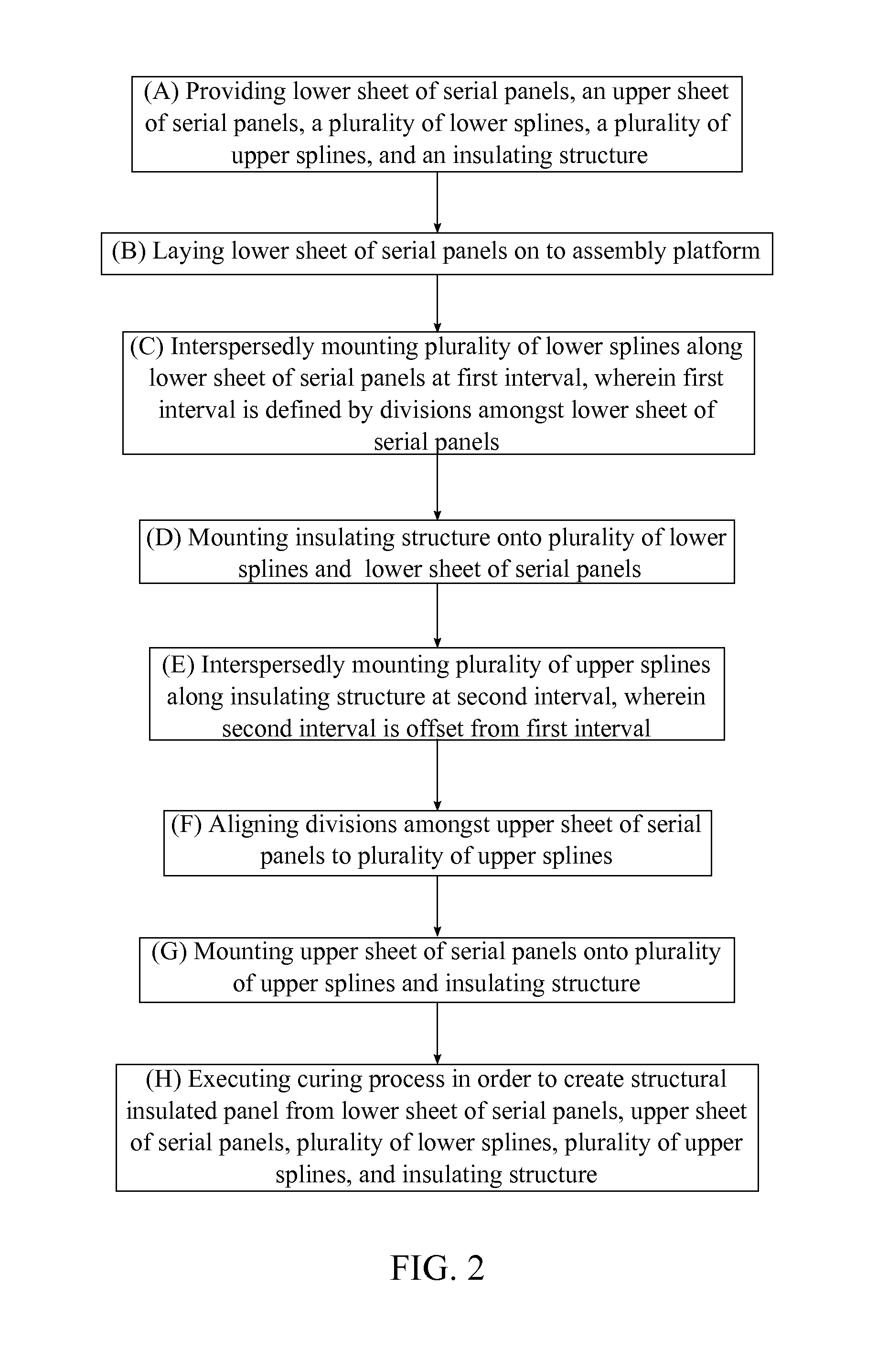
A method for manufacturing substantially longer structural insulated panels through lamination without sacrificing thermal efficiency and structural integrity. The method includes laminating an insulating structure in between a lower sheet of serial panels and an upper sheet of serial panels. The individual structural panels of the lower sheet of serial panels are spliced together with a plurality of lower splice plates. Similarly, the individual structural panels of the upper sheet of serial panels are spliced together with a plurality of upper splice plates. The plurality of upper splice plates is positioned offset from the plurality of lower splice plates. The resulting elongated structural insulated panel retains its characteristics due to the positioning of the splice plates and their integration into the manufacturing method.

Description

[0001]The current application claims a priority to the U.S. Provisional Patent application Ser. No. 61 / 943,578 filed on Feb. 24, 2014.FIELD OF THE INVENTION[0002]The present invention relates generally to methods for manufacturing structural insulated panels (SIPs). More specifically, the present invention provides is a process / technique for splicing multiple SIPs together without reducing the thermal efficiency and compromising the structural integrity.BACKGROUND OF THE INVENTION[0003]Structural insulated panels (SIPs) are load bearing sandwich panels that are manufactured using a high density foam core, most often expanded polystyrene (EPS), laminated with structural material on either side. When the SIP have been pressed and cured, the stressed skins form a load bearing building panel that handles structural loads similar to how an I-beam handles structural loading. The common skins used for SIPs include plywood, oriented strand board (OSB), magnesium oxide board, cement fiber, f...

Claims


Application Information

Patent Timeline
IPC IPC(8): B32B37/10B32B37/06B32B37/18
CPCB32B37/1027B32B37/18B32B37/06B32B2307/304B32B2325/00B32B2607/00B32B2305/022B32B37/02B32B37/1292B32B37/185B32B2307/7265B29C66/435
Inventor GILLMAN, JERRY
Owner GILLMAN JERRY
Learn More