
Handlebar support apparatus

a technology for supporting apparatus and hand-held video or still cameras, which is applied in the direction of travelling carriers, instruments, travelling articles, etc., can solve the problems of inconvenient adjustment, time-consuming and limited scope, and rudimentary and largely ineffective camera support systems, etc., and achieves compact size and weight.

Inactive Publication Date: 2009-11-24
ANTONBAUER
View PDF15 Cites 4 Cited by
  • Summary
  • Abstract
  • Description
  • Claims
  • Application Information

AI Technical Summary

Benefits of technology

"The present invention provides a support apparatus for optical recording devices that is compact, flexible, and easy to use. The apparatus includes a single or pair of flexible handles that can be easily attached to a camera or other support device. The handles have soft, deformable gripping portions that provide comfortable manipulation of the apparatus without impairing its adjustability. The apparatus can be used with different types of cameras and is particularly useful for handling cameras during filming or recording."

Problems solved by technology

However, most camera support systems are rudimentary and largely ineffective, while others are complicated and expensive.
Generally, known camera support systems employ rigid bars or un-yielding structural elements that are attached to a camera, therefore making their adjustment extremely difficult, time-consuming and limited in scope.
While such systems certainly may provide the rigidity and strength to support the weight of the camera unit during operation, it should be readily appreciated that the flexibility and orientation of known pipe support systems is severely restricted.
That is, as these systems are formed from rigidly connected pipe elements, the range of possible motion of the camera unit is inherently restricted to only those motions or orientations permitted by the innate structure of the system.
Once so mounted upon an operator, these known superstructures also have inherent restrictions as to the range of possible movement of the camera unit.
Moreover, the size and weight of these superstructures make their use difficult and laborious.
It will therefore be readily appreciated that known support systems for optical recording units are universally deficient as being fabricated from rigid and cumbersome constituent elements.
The rigidity of these constituent elements is such that the ability to position the optical recording unit as desired is oftentimes hampered by the lack of flexibility inherent in these known systems.

Method used


Image

  • Handlebar support apparatus
  • Handlebar support apparatus
  • Handlebar support apparatus

Examples


Embodiment Construction

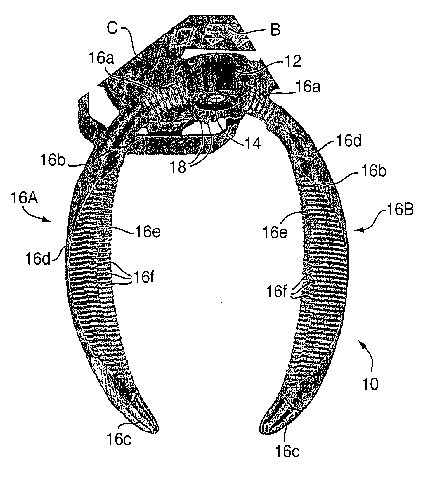
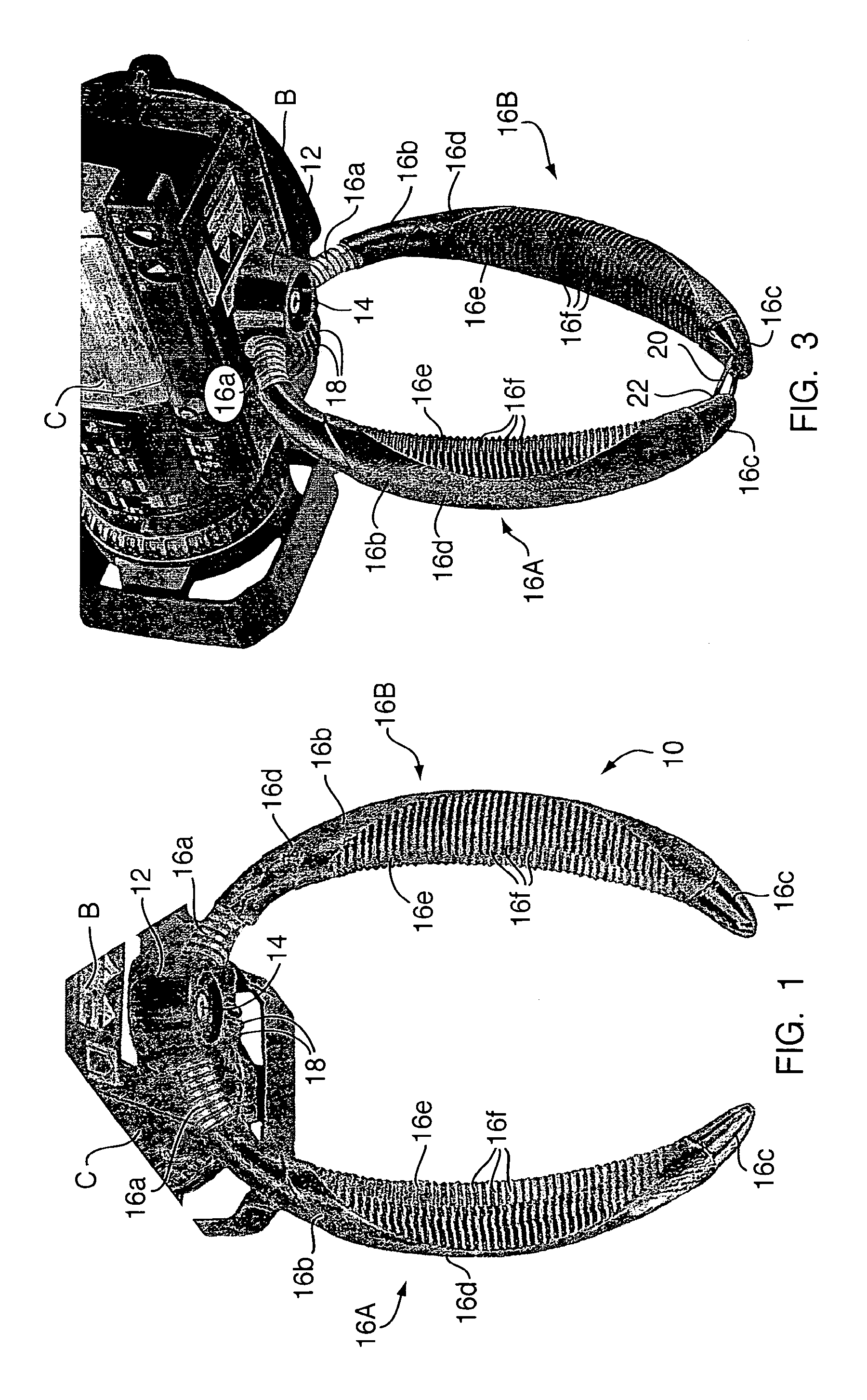
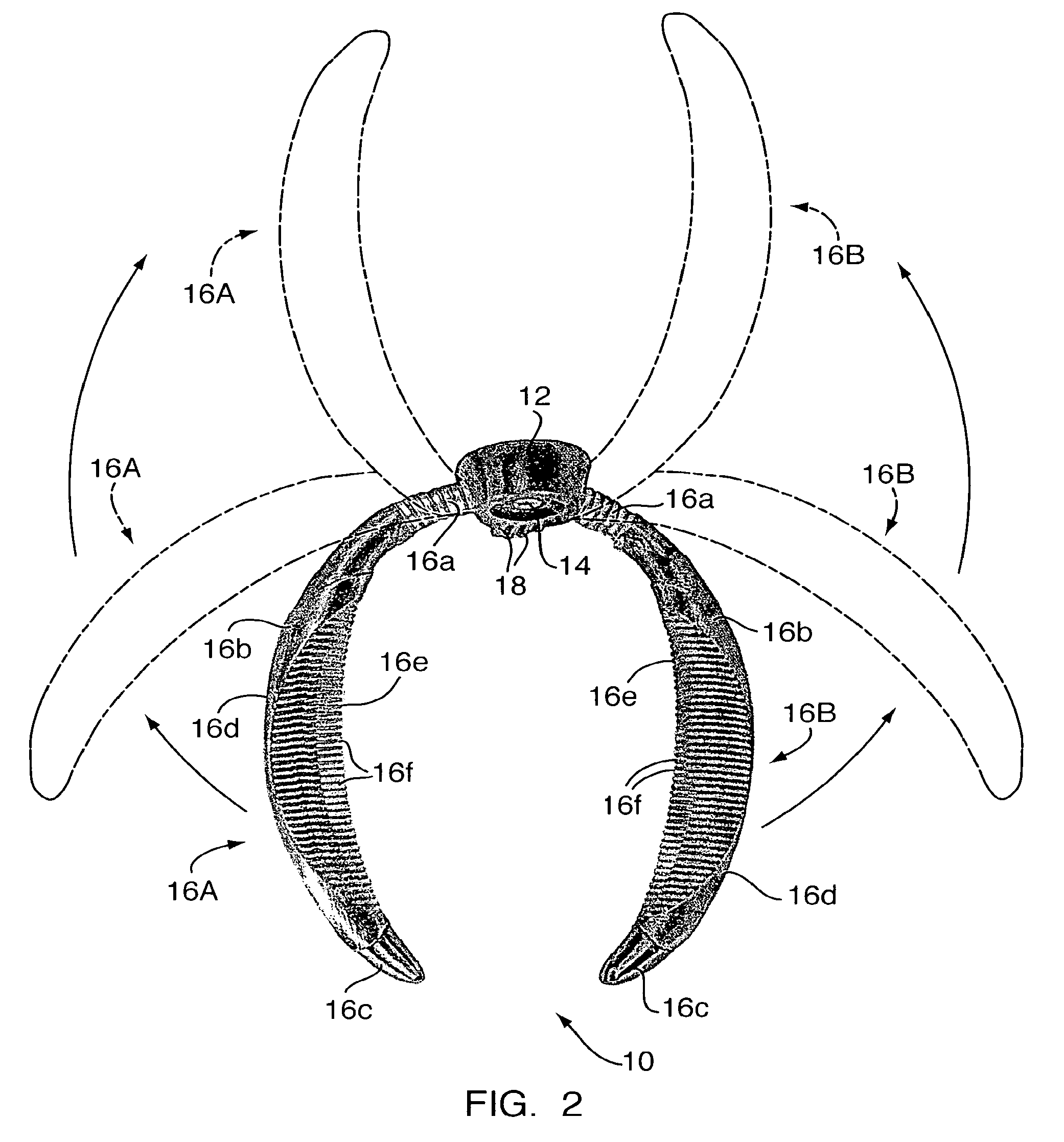
[0031]Referring first to FIGS. 1 and 2 of the drawings, handlebar support apparatus embodying a preferred form of the invention is generally indicated by 10 and is mounted on a base B of a camera C.

[0032]Handlebar support apparatus 10 includes an attachment means, such as a central circular hub 12, which is engageable with base B of camera C, either directly engagable via a threaded insert or stud or a similar mechanical engagement or fixation (not shown) provided on the base, or indirectly engagable through the use of an intermediary attachment means, such as those attachment means known as a quick release shoe and receive (also not shown). Moreover, it should be noted that support apparatus 10 may be attached to any intermediary means disposed between the support apparatus and the camera, such as a battery or accessory device.

[0033]A mounting means 14 is provided in hub 12 to permit the attachment of support apparatus 10 to such as a monopod, tripod, or other support, not shown. A...


PUM


Abstract

A fully adjustable, handlebar support apparatus is readily attachable to a hand held video or still camera or to another support device, such as a monopod or tripod and includes a flexible, articulating handle which may be grasped by the camera operator and selectively manipulated to exhibit an infinite range of possible contours to the flexible handle.

Description

FIELD OF THE INVENTION[0001]The present invention relates generally to optical recording devices, and more particularly to a support apparatus for hand held video or still cameras.BACKGROUND OF THE INVENTION[0002]A wide variety of support systems have been provided in the prior art for holding a hand held camera steady.[0003]However, most camera support systems are rudimentary and largely ineffective, while others are complicated and expensive. Generally, known camera support systems employ rigid bars or un-yielding structural elements that are attached to a camera, therefore making their adjustment extremely difficult, time-consuming and limited in scope.[0004]It is known in the art to provide a support system for a camera in which actual pipe or tube elements are joined together by known pipe fittings, such as right-angle fittings. While such systems certainly may provide the rigidity and strength to support the weight of the camera unit during operation, it should be readily appr...

Claims


Application Information

Patent Timeline
Patent Type & Authority Patents(United States)
IPC IPC(8): G03B17/00
CPCG03B17/563Y10S224/908
Inventor DESORBO, ALEXANDER P.
Owner ANTONBAUER
Learn More