Plasma-dome PDP

a technology of plasma shell and phosphor, which is applied in the field of plasma shell, can solve the problems of shortening the life of the phosphor and the pdp, and affecting the production efficiency of plasma shells. , the gas frit material or the wall of the microsphere may be too large to penetrate through the frit material or the wall of the microsphere,

Inactive Publication Date: 2009-11-24
IMAGING SYST TECH
View PDF215 Cites 20 Cited by
  • Summary
  • Abstract
  • Description
  • Claims
  • Application Information

AI Technical Summary

Problems solved by technology

The discharge between the two opposite electrodes generates electrons and ions that bombard and deteriorate the phosphor thereby shortening the life of the phosphor and the PDP.
Because of these residual gases, microspheres produced with this method are not acceptable for producing Plasma-spheres for use in a PDP.
Some gases such as xenon, argon, and krypton used in plasma displays may be too large to be permeated through the frit material or wall of the microsphere.
Because the shells cool and drop at the same time, the shell shells do not form uniformly.
It is also difficult to control the amount and composition of gas that remains in the shell.
However, shell uniformity may be difficult to control.

Method used


Image

  • Plasma-dome PDP
  • Plasma-dome PDP
  • Plasma-dome PDP

Examples


Embodiment Construction

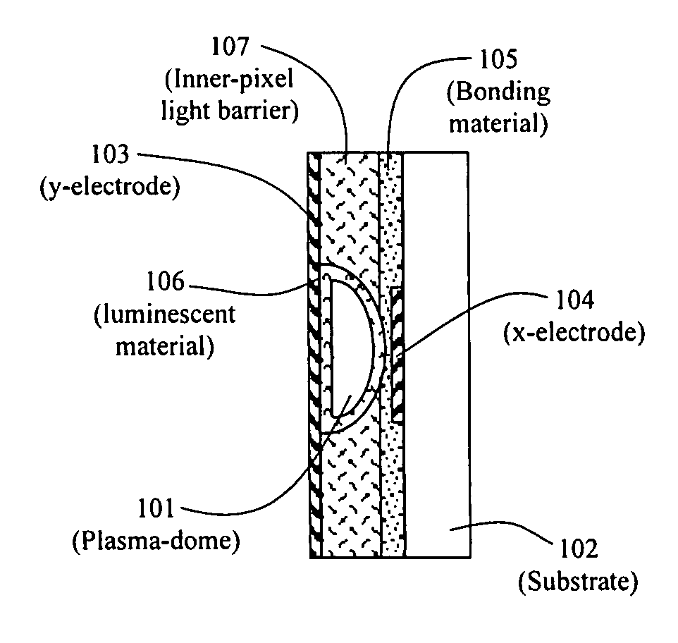
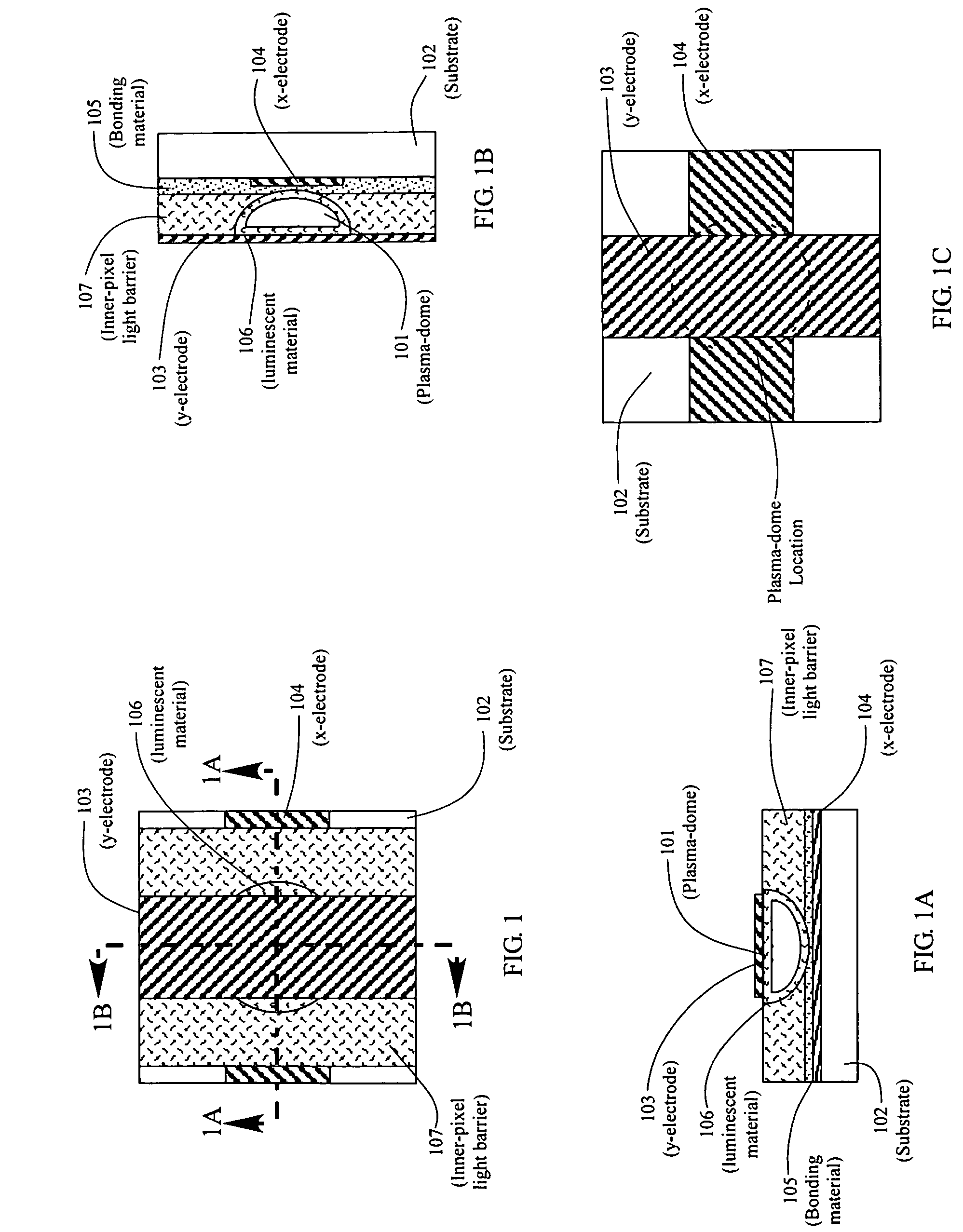
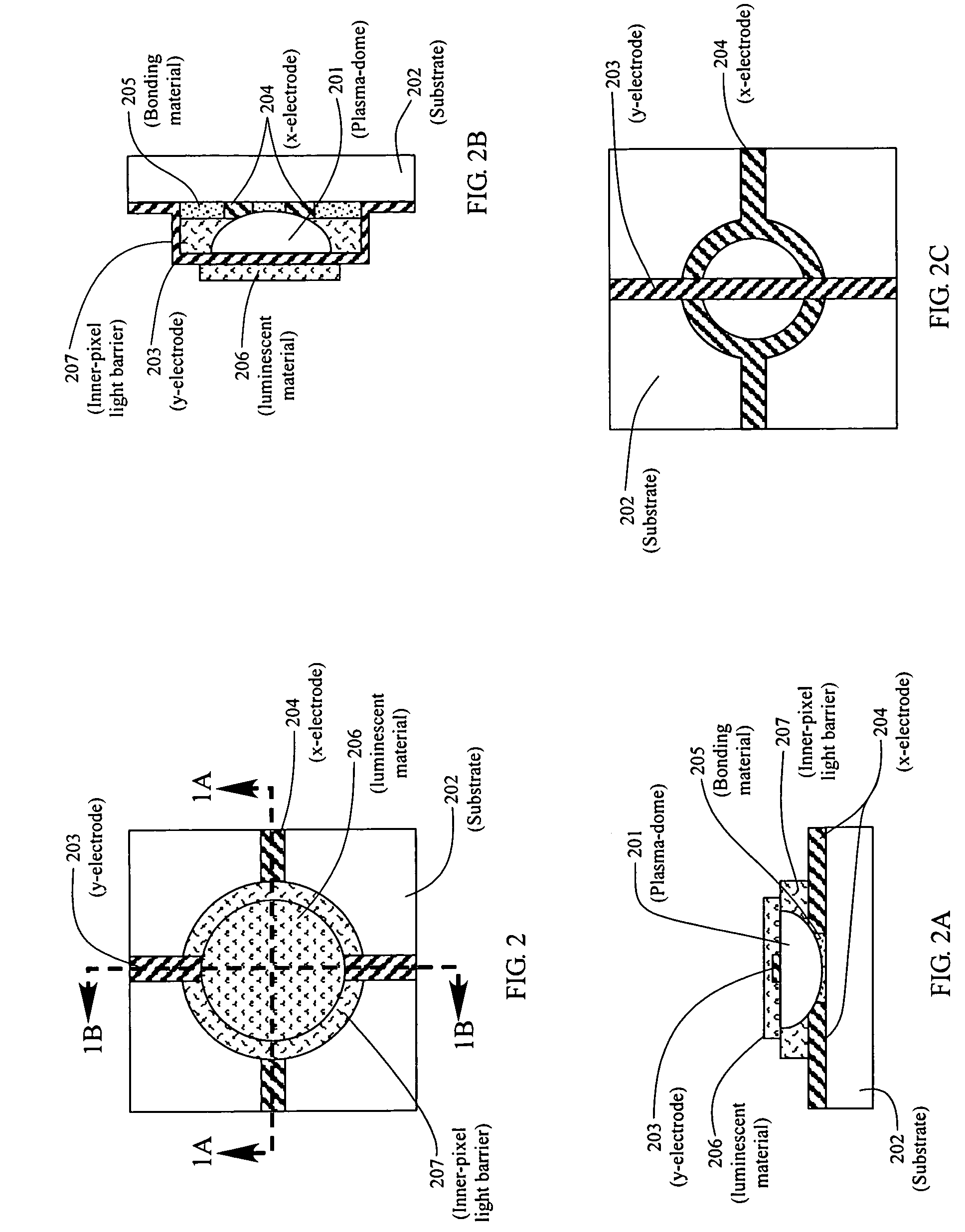
[0143]This invention relates to the positioning of Plasma-domes in or on a substrate in a plasma display panel (PDP) device. In accordance with this invention, at least two electrodes or conductors are electrically connected to a Plasma-dome located within or on a substrate. In one embodiment, an electrically conductive bonding substance is applied to each Plasma-dome and / or to each electrode so as to enhance the electrical connection of the electrodes to the Plasma-dome. In one embodiment, each electrically conductive bonding substance connection to each Plasma-dome is separated from each other by an insulating barrier so as to prevent the conductive substance from flowing and electrically shorting out another electrical connection. The Plasma-dome may be positioned on the substrate with a flat side or a domed side in contact with the substrate.

DETAILED DESCRIPTION OF DRAWINGS

[0144]FIG. 1 shows substrate 102 with transparent y-electrode 103, luminescent material 106, x-electrode 10...


PUM


Abstract

There is disclosed a plasma display panel (PDP) device having one or more substrates and a multiplicity of pixels or sub-pixels. Each pixel or sub-pixel is defined by a hollow Plasma-dome™ filled with an ionizable gas. The Plasma-dome has a flat side and an opposing domed side such as a flat bottom and a domed top or a flat rear and domed front. One or more other sides or edges may also be flat. Two or more addressing electrodes are in electrical contact with each Plasma-dome. A flat base side or domed side of the Plasma-dome shell is in contact with a substrate. The PDP may also include inorganic and organic luminescent materials that are excited by the gas discharge within each Plasma-dome. The luminescent material may be located on an exterior and / or interior surface of the Plasma-dome or incorporated into the shell of the Plasma-dome. Up-conversion and down-conversion materials may be used. The substrate may be rigid or flexible with a flat, curved, or irregular surface.

Description

RELATED APPLICATIONS[0001]Priority is claimed under 35 USC 119(e) for Provisional Application Ser. No. 60 / 654,462, filed Feb. 22, 2005.FIELD OF THE INVENTION[0002]This invention relates to the use of a Plasma-shell™ in a plasma display panel (PDP). As used herein, Plasma-shell™ includes Plasma-dome™, Plasma-disc™, and Plasma-sphere™, all trademarks of the assignee hereof. This invention particularly relates to Plasma-domes and the positioning of one or more Plasma-domes™ in contact with a PDP substrate and electrically connecting each Plasma-dome™ to electrical conductors such as electrodes. The hollow Plasma-domes™ are filled with an ionizable gas and are used as pixels or subpixels in a gas discharge plasma display panel (PDP) device. A Plasma-dome™ has a flat side with an opposite side that is domed. Other sides or ends of the Plasma-dome may also be flat or domed. A flat base side or a dome side of each Plasma-dome is in contact with the surface of a PDP substrate. The surface o...

Claims


Application Information

Patent Timeline
Patent Type & Authority Patents(United States)
IPC IPC(8): H01J17/49
CPCH01J11/22H01J11/18
Inventor WEDDING, CAROL ANNSTRBIK, III, OLIVER M.WEDDING, DANIEL K.
Owner IMAGING SYST TECH
Why Eureka
Try Eureka