Detection of deposits in steam humidifiers

a technology of humidifier and steam, which is applied in the direction of steam generation using steam absorption, combustion air/fuel air treatment, and boiler cleaning control devices, etc., can solve the problems of water damage to the structure, unhealthy conditions in the building, and liquid water within the duct can create a number of serious problems,

Active Publication Date: 2009-11-24
ADEMCO INC
View PDF10 Cites 32 Cited by
  • Summary
  • Abstract
  • Description
  • Claims
  • Application Information

AI Technical Summary

Problems solved by technology

An issue associated with humidification system is that they should only discharge water vapor into a duct and not liquid water.
Liquid water within a duct can create a number of serious problems.
For example, liquid water that remains stagnant within a duct can promote the growth of mold or organisms that can release harmful substances into the air flow, potentially causing unhealthy conditions in the building.
Liquid water can also cause rusting of a duct which can lead to duct failure, and can create leaks from the duct to the building interior spaces which are unsightly, can cause a slipping hazard, and can lead to water damage to the structure.
However, pressurized steam injection systems are associated with a risk of explosion of the steam pressure vessels, as well as a risk of possibly burning nearby people, both of which are very serious safety concerns.
In residential applications, there are usually no readily available sources of pressurized steam.
An open bath humidifier system may be used, however these are difficult to install because they require a large hole in the duct and can only be used with horizontal or upflow ducts.
Alternatively, a residential application may use direct steam injection, but this requires a separate unit to generate pressurized steam and this separate unit is costly.
Moreover, the system would suffer from the same disadvantages as are present in commercial direct steam injection systems.
In this type of humidifier, heat is generated within a tank of water, causing the water to boil and steam to be generated.
One problem associated with this type of humidifier is that as water is boiled off as steam, the impurities in the water remain in the tank.
Over time, the concentration of these impurities will tend to increase in the tank, leading to greater amounts of impurities that solidify and deposit on the surfaces inside the tank.
These deposits can accumulate to the point of creating numerous problems.
For example, deposits on a heating coil reduce the heat transfer rate to the water, resulting in lower steam production and possibly causing overheating and failure of the coil.
Deposits in the tank can clog passages where water or steam flows in or out, resulting in the failure of the humidifier.

Method used


Image

  • Detection of deposits in steam humidifiers
  • Detection of deposits in steam humidifiers
  • Detection of deposits in steam humidifiers

Examples


Embodiment Construction

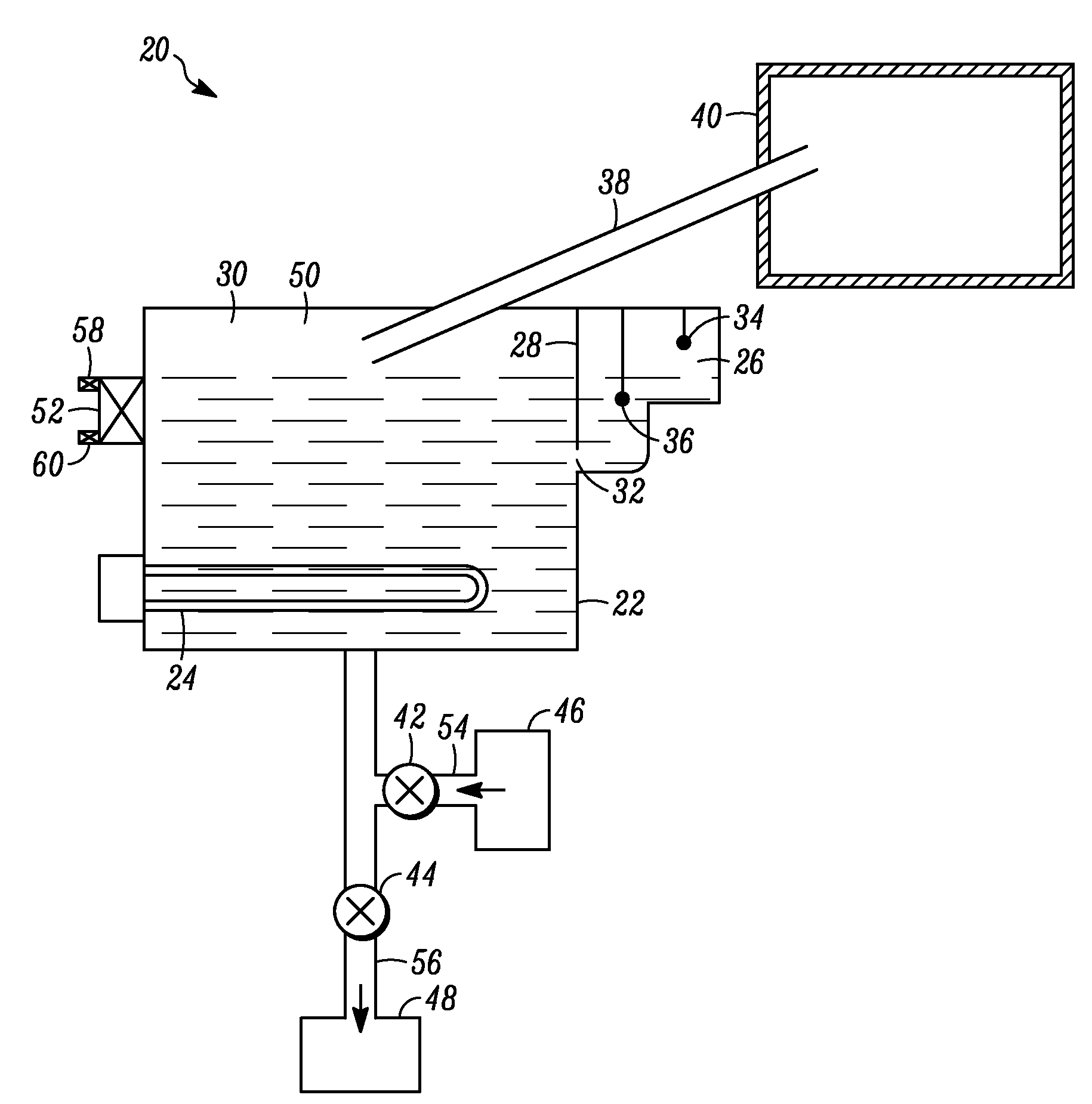
[0016]As described above, minerals, sediments, and other impurities present in water tend to deposit in the tank of a tank heater type humidifier over the course of its operation. These deposits can build up and cause damage and interfere with the proper functioning of the humidifier. However, the rate at which these deposits form depend on a number of variables, including the mineral content of the water (hardness) and the amount of time that the humidifier is operated. In some cases, it is recommended that the user of a humidifier disassemble and manually clean the tank and associated parts at a regular interval, such as every year. This strategy, however, fails to account for the variability in the rate at which deposits form, such that in some cases the tank is cleaned more often than it needs to be, and in others, the tank is not cleaned often enough and consequently the humidifier fails. This strategy also is dependent upon the user actually cleaning the tank, which in many ca...


PUM

PropertyMeasurementUnit
operating timeaaaaaaaaaa

Abstract

A humidifier configured to determine when the humidifier requires cleaning. The humidifier includes a tank for containing water, a heater for heating the water in the tank to generate steam, and one or more water level sensors for detecting the level of water in the tank, including detecting water at first level and a second level, where the first level is lower than the second level. The humidifier further includes a drain valve for draining water from the tank and a controller. The controller is configured to open the drain valve to drain water from the tank, measure a time interval required for the water to drain from the second level to the first level, and compare the time interval against a threshold value. If the time interval exceeds the threshold value, then the controller is configured to provide an indication to clean the humidifier. Methods are also disclosed.

Description

FIELD OF THE INVENTION[0001]The invention relates to humidification systems. More particularly, the invention relates to steam humidifier systems and the detection of deposits and accumulations within a humidifier.BACKGROUND OF THE INVENTION[0002]The interior spaces of buildings are often at a lower than desired level of humidity. This situation occurs commonly in arid climates and during the heating season in cold climates. There are also instances in which special requirements exist for the humidity of interior spaces, such as in an art gallery or where other delicate items are stored, where it is desired that the interior humidity levels be increased above naturally occurring levels. Therefore, humidifier systems are often installed in buildings to increase the humidity of an interior space.[0003]Humidification systems may take the form of free-standing units located within individual rooms of a building. More preferably, humidification systems are used with building heating, ven...

Claims


Application Information

Patent Timeline
Patent Type & Authority Patents(United States)
IPC IPC(8): A01G13/06F24F3/14
CPCF22B37/56F22B1/284
Inventor LENTZ, TRACY L.HOGLUND, STEVEN R.
Owner ADEMCO INC
Why Eureka
Try Eureka